
Page 274 - APPLIED PROCESS DESIGN FOR CHEMICAL AND PETROCHEMICAL PLANTS, Volume 1, 3rd Edition
P. 274
246 Applied Process Design for Chemical and Petrochemical Plants
D,,,, = 4(5.01)/[2.828 + 2n: (1.5) - 3.691 = 2.34ft There are basically three construction types for
impingement separators:
v,~,,,, = 0.187/5.01 = 0.0373 ft/sec
1. Wire mesh
2. Plates (curved, flat or special shaped)
3. Packed Impingement Beds
d = droplet diameter, ft
Knitted Wire Mesh
The degree of turbulence would be classified as accept-
able, but the unit must not be increased in capacity for A stationary separator element of knitted small diame-
fear of creating more water phase turbulence. ter wire or plastic material is formed of wire 0.003 in. to
0.016 in. (or larger) diameter into a pad of 4 inches, 6
inches or 12 inches thick and serves as the impingement
B. Impingement Separators
surface for liquid particle separation. Solid particles can
be separated, but they must be flushed from the mesh to
As the descriptive name suggests, the impingement prevent plugging. Although several trade name units are
separator allows the particles to be removed to strike available they basically perform on the same principle,
some type of surface. This action is better accomplished and have very close physical characteristics. Carpenter [4]
in pressure systems where pressure drop can be taken as a presented basic performance data for mesh units. Figure
result of the turbulence which necessarily accompanies 415 shows a typical eliminator pad.
the removal action.
Figure 416 pictorially depicts the action of the wire
Particle removal in streamline flow is less efficient than mesh when placed in a vertical vessel.
for turbulent flow, and may not be effective if the path of Referring to Figure 41 6, the typical situation repre-
travel is not well baffled. sents a vapor disengaging from a liquid by bursting bub-
The “target” efficiency for impingement units express- bles and creating a spray of liquid particles of various
es the fraction of the particles in the entraining fluid, sizes. Many of these particles are entrained in the moving
moving past an object in the fluid, which impinge on the vapor stream. The largest and heaviest particles will settle
object. by gravity downward through the stream and back to the
bottom of the vessel or to the liquid surface. The smaller
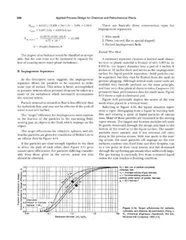
The target efficiencies for cylinders, spheres, and rib- particles move upward, and if not removed will carry
bonlike particles are given for conditions of Stokes Law in along in the process stream. With wire mesh in the mov-
an infinite fluid by Figure 414.
ing stream, the small particles will impinge on the wire
If the particles are close enough together in the fluid surfaces; coalesce into fluid films and then droplets, run
to affect the path of each other, then Figure 414 gives to a low point in their local system; and fall downward
conservative efficiencies. For particles differing consider- through the up-flowing gas stream when sufficiently large.
ably from those given in the curves, actual test data The gas leaving is essentially free from entrained liquid
should be obtained. unless the unit reaches a flooding condition.
’ Db = Min. dia. of particle completely
collected, feet
V, = Average velocity of gas, feet/sec.
ut = Terminal settling velocity of
particle under action of gravity, feet/sec.
gL = 32.2 feetlsec.2
Figure 4-14. Target efficiencies for spheres,
cylinders, and ribbons. By permission, Perry, J.
0.01 0.1 1 .o 10 100 H., Chemical Engineers Handbook, 3rd Ed.,
Separation Number, ulVo/gLDb McGraw-Hill Company, 1950 [13].