
Page 279 - APPLIED PROCESS DESIGN FOR CHEMICAL AND PETROCHEMICAL PLANTS, Volume 1, 3rd Edition
P. 279
echanical Separations 251
solids build-up can become appreciable, and is usually the special situations have been placed at an angle to the hor-
guide or indicator for cleaning of the mesh. A 12-inch pad izontal, but these usually accumulate liquid in the lower
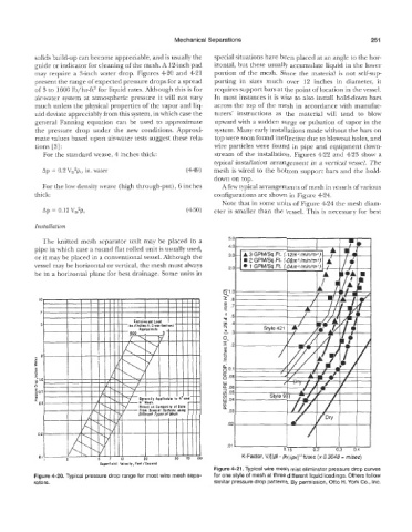
may require a %inch water drop. Figures 4-28 and 421 portion of the mesh. Since the material is not self-sup-
present the range of expected pressure drops for a spread porting in sizes much over 12 inches En diameter, it
of 3 to 1600 lb/hr-f12 for liquid rates. Although this is for requires support bars at the point of location in the vessel.
air-water system at atmospheric pressure it will not vary In most instances it is wise to also install hold-down bars
much unless the physical properties of the vapor and liq- across the top of the mesh in accordance with manufac-
uid deviate appreciably from this system, in which case the turers' instructions as the material will tend to blow
general Fanning equation can be used to approximate upward with a sudden surge or pulsation of vapor in the
the pressure drop under the new conditions. Approxi- system. Many early installations made i~yithout the bars on
mate values based upon air-water tests suggest these rela- top were soon found ineffective due to blowout holes, and
tions [3]: wire particles were found in pipe and equipment down-
weave. 4 inches thick: stream of the installation. Figures 422 and 4-23 show a
typical installation arrangement in a vertical vessel. The
Ap = 0.2 VDzpw, in. water (449) mesh is wired to the bottom support bars and the hold-
down on top.
For the low density weave (high through-put) , 6 inches A few typical arrangements of mesh in vessels of various
thick: configurations are shown in Figure 424.
Note that in some units of Figure 424 the mesh diam-
Ap = 0.12 VD2p, (450) eter is smaller than the vessel. This is necessary for best
Installation
The knitted mesh separator unit may be placed in a
pipe in which case a sound flat rolled unit is usually used,
or it may be placed in a conventional vessel. Although the
vessel may be horizontal or vertical, the mesh must always
be in a horizontal plane for best drainage. Some units in
.01
K-Factor, VI[(@ pv)/pv]'"Wsec (x 0.3048 = m/sec)
-
Figure 4-21. Typical wire mesh mist eliminator pressure drop cuwes
. Typical p~~essure drop range for most wire mesh sepa- for one style of mesh at three different liquid io
rators* similar pressure drop patterns. By permission,