Page 282 - APPLIED PROCESS DESIGN FOR CHEMICAL AND PETROCHEMICAL PLANTS, Volume 1, 3rd Edition
P. 282

254                       Applied Process Design for Chemical and Petrochemical Plants

                                                                            'dire  ?htra,inaont  Xesh  SDecifications
                                                                     A.  Applicntion  Service
                                                  uni, Pric.
            VU No.                                                     1.   Source  of 3ntrainment:
                              DRUM OR TANK SPECIFICAT~NI   n -
                                                  I.."  Y..            2.  Operatin7 Conditions:   Give  (1)  Formal  (2) &.ximum
                                                                                          (3) I<inirrm,  where  possible
                                                                         Te:.oerature
                                                                         Pr-ssure
                                                                         Vapor Phase
                                                                            Flow Rate
                                                                            *Vel0 ci ty
                                                                            Density              at operatin_r conditions
                                                                            i .o  le cular Yeirht
                                                                             Coiposition  or Kature  of  Pbse
                                                                          Lipaid  Zntninaent  Phase
                                                                             Quantity (if known) :
                                                                             Dens1 ty :
                                                                             ViocositJ:
                                                                             Surface  Tension:
                                                                             Composition  or Uiture  of Entrainnent:
                                                                             Droglet  Sizes or distribution  (if known):
                                                                             Solids  Content  (Composition and  Quantity):
                                                                               Dissolved:
                                                                                3r;spended:
                                                                       3.  Perfornance
                                                                          AllonaSle  Totil  Separator  Pressure Dro?:
                                                                          Allowable  Xesh  Pressure Drop:
                                                                          Allorrible  Entralment :
                                                                          Yeah  Thickness  Recomended:
                                                                      E.  Construction and Installation

            BY      1 ChhY   I I.".   I I...   I R.V.   I h..   I      1.  Vessel                Lensth
                                                                          *Dia*ae t er . I. D:
            I.*     I       I       I        I       I
            P.O. T.:                                                       Construction Yaterial:
                                                                          +Position  (Eorizontal,  Vertical,  Inclined):
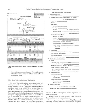
             Figure 4-25.  Specification  design  sheet  for  separator  using  wire
             mesh.                                                        +Shape  (Circular,  Square,  etc.):
                                                                           Type  (5'vepor3tor,  Still,  Drum.  etc.):
                                                                           Existing or Proposed:
                 Heavy oil with suspended matter. This might plug. A   2.  ESltrsim.ent  Nesh
                 light oil or solvent spray would be recommended for      Construction Xaterial
                 flushing the mesh.                                          Separator  Kesh

                                                                             Support  Grid
             Fiber Beds/Pads Impingement Eliminators                      Installation  Kethod  (Dlaensions)
                                                                             Vessel  Open  End:
               The use of fiber packing held between wire mesh con-          &$anhole (size):
             taining  screens  is  best  applied  in  the  very  low  micron   C.   S?ecial  Conditions:
             range,  generally  0.1  to  >  3  microns  with  recoveries  of   *Assumes  vessel  size  fixed  prior  to mesh  lnoulry
             entrained liquid of up to 99.9'7% (by weight). Figures 4    Figure 4-26. Wire entrainment mesh specifications.
             27A, B, and C illustrate the design concept and its corre-
             sponding data table indicates expected performance. The
             fibers used mean the bed packing can be fabricated from   removed  by  direct interception,  inertial impaction, and
             fine glass, polypropylene fibers, or can be selected to be   Brownian capture.
             the  most  resistant  to  the  liquid  mist  entering  the  unit   The design rating for this equipment is best selected by
             from  corrosive  plant  operations  such  as  sulfuric  acid,   the manufacturers for each application.
             chlorine, nitric acid, ammonia scrubbing for sulfur oxides   The concept of removal of entrained liquid particle is
             control,  and  many  others.  The  entrained  particles  are   essentially the same as for wire mesh designs, except the
   277   278   279   280   281   282   283   284   285   286   287