
Page 281 - APPLIED PROCESS DESIGN FOR CHEMICAL AND PETROCHEMICAL PLANTS, Volume 1, 3rd Edition
P. 281
Mechanical Separations 253
t
-+
=I---
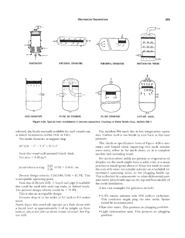
HORIZONTAL SEPARATORS HORIZONTAL SEPARATORS
?
iM-LINE GAS SCRUBBERS OIL-GAS SEPARATORS OVER-SIZE VESSEL
Figure 41-24. Typical mesh installations in process equipment. Courtesy of Metal Textile Gorp., Bulletin ME-7.
selected, the heads normally available for such vessels run Use stainless 304 mesh due to low temperature opera-
in 6-inch increments (either Q.D. or I.D.). tion. Carbon steel is too brittle in wire form at this tem-
Net inside diameter at support ring: perature.
The check or specification form of Figure 426 is nec-
. - 4” - 3,/4” = 25 1/4“ essary and helpful when inquirying wire mesh entrain-
ment units, either as the mesh alone, or as a complete
Note that vessel wall assumed %inch thick. turnkey unit including vessel.
Net area = 3.46 sq ft
For services where solids are present or evaporation of
droplets on the mesh might leave a solid crust, it is usual
practice to install sprays above or below the mesh to cover
Actual velocity at ring: 2.83 (2.74) = 2.24 ft / sec
3.46 the unit with water (or suitable solvent) on scheduled (or
necessary) operating times, as the plugging builds up.
esign melocity: 2.24(100)/3.66 = 61.3%. This This is checked by a manometer or other differential pres-
is acceptable operating point. sure meter placed with taps on the top and bottom side of
Note that if 28-inch O.D. X %-inch ~7all pipe is available the mesh installation.
this could be used with weld cap ends, or dished heads. A few case examples for guidance include:
The percent design velocity would be = 71.8%.
This is also an acceptable design.
Pressure drop is in the order of 0.1 inch to 0.5 inches 0 2-3% caustic solution with 10% sodium carbonate.
This condition might plug the wire mesh. Sprays
water. would be recommended.
Notes: Since this vessel will operate as a flash drum with
a liquid level at approximately >i of its height up from e Raw river water. This presents no plugging problem
bottom, place the inlet at about center of vessel. See Fig- Light hydrocarbon mist. This presents no plugging
ure 4-25. problem