
Page 286 - APPLIED PROCESS DESIGN FOR CHEMICAL AND PETROCHEMICAL PLANTS, Volume 1, 3rd Edition
P. 286
258 Applied Process Design for Chemical and Petrochemical Plants
3. Note that some units use pipe line size for the sepa-
rator size designation, others do not.
4. From the system operating pressure, establish the pres
sure rating designation for the separator selection.
5. Note that most separators for pressure system opera-
tions are fabricated according to the ASME code.
6. Specify special features and materials of construc-
tion, such as alloy or nonferrous impingement parts,
or entire vessel if affected by process vapor and liq-
uid. SpeciEj special liquid reservoir at base of unit if
necessary for system operations. Line units normally
have dump traps or liquid outlet of separator, while
vessel type often use some type of liquid level control.
7. Specification sheet: see Figure 433.
FLOW LEGEND
CONTAMINATED PRODUCT
C$EZ WATER
e DRY PRODUCT
CLEAN
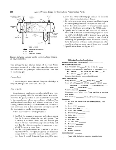
Figure 4-32. Typical coalescer unit. By permission, Facet Enterpris-
es, Inc., Industrial Div.
Bsffle !bne Seuarator Sueclficatlona
Sewrator ApPllcstlon: (Give Service) ~
very peculiar to the internal design of the unit. Some Desian Oueratizw Conditions:
units are guaranteed to reduce mechanical entrainment %in Stream Flow Rate ___ Sp. Or. or Elol. Ht. -
loss to less than 0.1 gallon per million standard cubic feet %trained Material rate(1r knom)source or entrainment -
of entraining gas. Min. Pressure __psi (g) or (a), ax. Temp. O F .
&wax. hessure - (9) or (a)
psi
%trained Particle elm (mesh)(Plcrons)
Pressure Drop
Vessel Sueotficationa:
PSI
OF.
Pressure drop in most units of this general design is Design Pressure - - Design Temp. -
1950 M. -
A9ME
very low, being in the order of 0.1 to 3 psi. C04-3: *PI-ASME - 1949 Ed. -Am
State Code -: lion-Code -, Customeh Spec. -
X-Ray - Stress Relief -
How to Specafj
Corrbsion sllowande
Dimenalons: - x __ " long bend llne to bend line
'O.D.
Manufacturers' catalogs are usually available and com-
plete with capacity tables for the selection of a unit size. Base Support
However, it is good practice to have this selection checked Mist Extrabtor: , Mat'l. 02 Construction
by the manufacturer whenever conditions will allow. This Connections
avoids misunderstandings and misinterpretations of the 1. (la6 inlet and outlet:(Slse. ABa nressure rstlna. tvW
catalog, thereby assuring a better selection for the separa- -1
tion operation, and at the same time the experience of 2. Llquid outlet
the manufacturer can be used to advantage. 3. Liquid Level Qasge
4. Liquld Level Control
With a manufacturer's catalog available:
5. Pressure Gauge
6. Relief Valve
1. Establish the normal, maximum, and minimum gas
flow for the system where the unit will operate. This 7. Bursting Disc
is usually in standard cubic feet per minute, per 8. Hl& Level Alarm
hour or per day. Note the catalog units carefully, and 9. low Level Alarm
also that the reference standard temperature is usu- 10. Thermometer
ally 60°F for gas or vapor flow. 11. Equalizer
2. Use the rating selection charts or tables as per cata- 12. Drain
log instructions. For specific gravity or molecular 13. Others:
weight different than the charts or tables, a correc- Suealal Features:
tion factor is usually designated and should be used. Figure 4-33. Baffle-type separator specifications.