
Page 288 - APPLIED PROCESS DESIGN FOR CHEMICAL AND PETROCHEMICAL PLANTS, Volume 1, 3rd Edition
P. 288
260 Applied Process Design for Chemical and Petrochemical Plants
(4-52)
N, has been found to be about 5 turns of the gas stream
in the unit, and is considered somewhat conservative.
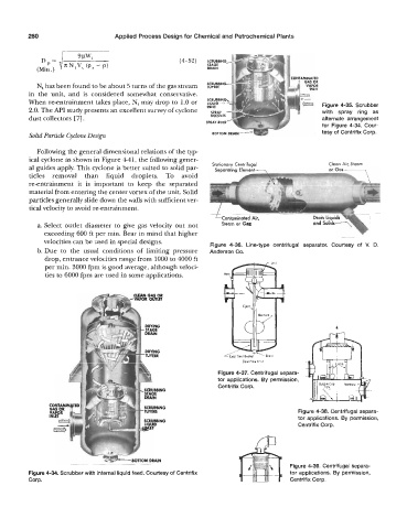
When re-entrainment takes place, N, may drop to 1.0 or Figure 4-35. Scrubber
2.0. The API study presents an excellent survey of cyclone with spray ring as
dust collectors [VI. alternate arrangement
for Figure 4-34. Cour-
Solid Particle Cyclom Design tesy of Centrifix Corp.
Following the general dimensional relations of the typ
ical cyclone as shown in Figure 441, the following gener-
al guides apply. This cyclone is better suited to solid par- Stationary Centrifugal Cleon Air, Steam
ticles removal than liquid droplets. To avoid
re-entrainment it is important to keep the separated
material from entering the center vortex of the unit. Solid
particles generally slide down the walls with sufficient ver-
tical velocity to avoid re-entrainment.
a. Select outlet diameter to give gas velocity out not Steam or G-
exceeding 600 ft per min. Bear in mind that higher
velocities can be used in special designs. Figure 4-36. Line-type centrifugal separator. Courtesy of V. D.
b.Due to the usual conditions of limiting pressure Anderson Co.
drop, entrance velocities range from 1000 to 4000 ft
per min. 3000 fpm is good average, although veloci-
ties to 6000 fpm are used in some applications.
c
Downflow Unit
Figure 4-37. Centrifugal separa-
tor applications. By permission,
Centrifix Corp.
Figure 4-38. Centrifugal separa-
tor applications. By permission,
Centrifix Corp.
BOTTOM DRAIN
Figure 4-39. Centrifugal separa-
Figure 4-34. Scrubber with internal liquid feed. Courtesy of Centrifix tor applications. By permission,
Corp. Centrifix Corp.