
Page 292 - APPLIED PROCESS DESIGN FOR CHEMICAL AND PETROCHEMICAL PLANTS, Volume 1, 3rd Edition
P. 292
264 Applied Process Design for Chemical and Petrochemical Plants
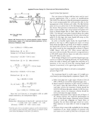
k 18' -I Air Out Liquid Cy clone-Type Separator
nt
The unit shown in Figure 449 has been used in many
Inlet r- process applications with a variety of modifications
--k
[ 18,19,20]. It is effective in liquid entrainment separation,
Fan Discharge
66.67 cu. ft./sec. but is not recommended for solid particles due to the
arrangement of the bottom and outlet. The flat bottom
plate serves as a protection to the developing liquid sur-
face below. This prevents re-entrainment. In place of the
plate a vortex breaker type using vertical cross plates of 4
inch to 12-inch depth also is used, (Also see Reference
[58] .) The inlet gas connection is placed above the outlet
Note:This is Not Drawn & dip pipe by maintaining dimension of only a few inches at
to Scale.
Dust 1 Out point 4. In this type unit some liquid will creep up the
walls as the inlet velocity increases.
Figure 4-48. Pressure drop for cyclone separator system. Adapted
by permission, Lapple, C. E., Fluid and Particle Dynamics, 1 st Ed., In order to handle higher loads, the liquid baffle is
University of Delaware, 1954. placed at the top to collect liquid and cause it to drop
back down through the gas body. If the baffle is omitted,
the liquid will run down the outlet pipe and be swept into
Loss = (0.204) (.5) = 0.102 in. water
the outlet nozzle by the outgoing gas as shown in Figure
4-50B. Figure 4-50 and 4-51 show several alternate
Friction Loss @ to @ : entrance and exit details. The unit with a tangential entry
Assume as 1 vel. head (conservative)
is 30%-60% more efficient than one with only a turned-
down 90" elbow in the center.
Friction loss = (1) (.50) = 0.50 in. water
If the design of Figure 441 is used for liquid-vapor sep-
aration at moderately high liquid loads, the liquid sliding
Friction Loss @ to @ (thru cyclone):
down the walls in sheets and ripples has somewhat of a
tendency to be torn off from the rotating liquid and
become re-entrained in the upward gas movement.
Liquid Cyclone Design (Based on air-water at atmospheric
pressure) Figure 4-49
Friction loss = 8.0(0.25) = 2.0 in. water
For maximum liquid in outlet vapor of 4 weight per-
Friction Loss @ to @ :
cent based on incoming liquid to separator: Figure 449.
NRe = 280,000, f = 0.004
a. Select inlet pipe size to give vapor velocity at inlet of
100 to 400 ft per second for tangential pipe inlet.
4fL (4) (.004) (4.5) b. Select separator diameter to give velocity of 0.02 to
No. vel. heads = _. =
D 2 0.2 (max.) times the inlet velocity. At 400 feet/sec-
= ,036 vel. head
ond pipe velocity the separator velocity should be
0.018 to 0.03 times the pipe velocity. At 130 feet/sec-
Loss = 0.036(.10) = 0.0036 in. water
ond pipe velocity the separator velocity should be
0.15 to 0.2 times the pipe velocity.
Since the unit exhausts to atmosphere with no addi-
tional restrictions, the total pressure drop is: c. Establish dimensions from typical unit of Figure 4
49. Always evaluate the expected performance in
terms of the final design, adjusting vertical dimen-
AP (total) = sions to avoid gas whipping on liquid films or
Friction loss + downstream vel. head at 0- upstream vel. head droplets. Do not direct inlet gas toward an outlet.
(0.102 + 0.50 + 2.0 + 0.0036) + 0" - 0.50 Place manway on same side of vessel as tangential
AP (total) = 2.6056 + 0 - 0.50 = 2.10 in. water
inlet.
d. Pressure drop is essentially negligible for the average
*Note that point (5) is at atmospheric pressure and the velocity head is
zero; however, if there had been a back pressure or resistance at this conditions of use. Some estimate of entrance and
point before discharging it would have to be added in. exit losses can be made by fluid flow techniques, and