
Page 293 - APPLIED PROCESS DESIGN FOR CHEMICAL AND PETROCHEMICAL PLANTS, Volume 1, 3rd Edition
P. 293
Mechanical Separations 265
VmpartDut T
Inlet
.._. .+.-
(Also Designed to Wrap
98. to 180’ Around Vessel
Io give Tangential Inlrtl.
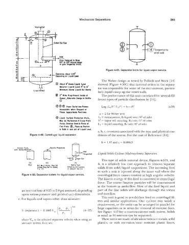
Figure 4-51. Separator inlets for liquid-vapor service.
The Webre design as tested by Pollock and Work [ 141
@ About 6” Above Liquid Level showed (Figure 450C) that internal action in the separa-
Maintain Liquid Level 4“ to 12“ tor was responsible for some of the entrainment, particu-
LiQuid b 10ut Minimum Above Liquid Out Nozzle larly liquid creep up the vessel walls.
2* Wide Ring Around lnridr at The performance of this unit correlated for several dif-
Vnsrd , Altcrnotr Design 10 Baffle ferent types of particle distribution by [14]:
Q
8 @ @ Vapor Outlet has Proven Log [&.(V’/Ll)a] = b t cV’ (458)
Acceptable when Stopped at
Theta Approximata Positions.
a = 2 for Webre unit
0 Liquid Surface Protection Plate, L, = entrainment, lb liquid/min/ft2 of inlet
May be Perforatd.lf Cross-Plate V‘ = vapor vel. entering, Ib/min/ft2 of inlet
Vartrr Ereoker Used in Place of L, = liquid entering, lb/min/ft2 of inlet
Place
Flat plate 0, sa Portion
i5 Both in ond out of Liquid Lmvel.
a, b, c, constants associated with the type and physical con-
igure 4-49. Centrifugal liquid separator. ditions of the system. For the unit of Reference [14]:
b = 1.85 and c = 0.00643
Nozzle Flus ozrla Projects in
with Inside She
Inlet
c Liquid-Solids Cyclone (Hydrocyclones) Separators
ITonqentiall
Liqui out
ou This type of solids removal device, Figures 452A, and
(AI IB) IC) B, is a relatively low cost approach to remove/separate
Not Much Eeiler than (AI Webre Type
Unless Ring Boffle Added, Effective, Particulaily solids from solid/liquid suspensions. The incoming feed
Fig. - 27. in Vacuum Service
to such a unit is injected along the inner wall where the
Figure 4-50. Sep,arator outlets for liquid-vapor service. centrifugal force causes rotation at high angular velocity.
The kinetic energy of this feed is converted to centrifugal
force. The coarse/heavier particles will be concentrated
at the bottom as underflow. Most of the feed liquid and
an internal loss of 0.25 to 2.0 psi assumed, depending part of the fine solids will discharge through the vortex
upon system pressure and general unit dimensions. and overflow.
This unit is good to pre-thicken feed to centrifugal fil-
e. For liquids and vapors other than air-water:
ters and similar applications. One cyclone may satisfj a
requirement, or the units can be arranged in parallel for
large capacities or in series for removal of extreme fines.
See Figure 453 for a counter-current wash system. Solids
as small as 10 microns can be separated.
where Vsa is the selected separator velocity when using an These units are made of abrasion resistant metals, solid
air-water system, feet/sec. plastics, or with corrosion/wear resistant plastic liners,