
Page 289 - APPLIED PROCESS DESIGN FOR CHEMICAL AND PETROCHEMICAL PLANTS, Volume 1, 3rd Edition
P. 289
Mechanical Separations 261
c. Select cylindrical shell diameter, D,, with two consid-
erations in mind:
Typical estimating efficiencies are given in Figures 446
Large diameter reduces pressure drop and 447. Note the curves indicate how much dust of each
Small diameter has higher collection efficiency for particle size will be collected. The efficiency increases as
the same entrance conditions and pressure drop. the pressure drop increases; that is, a smaller separator
might have a higher efficiency due to the higher gas
d. The length of the inverted cone section, Z,, is critical, velocities and increased resistance than a larger unit for
although there is no uniformity in actual practice. The the same gas flow. For example, there are several curves
dimensions suggested in Figure 4-41 are average. of the typical shape of Figure 446, with each curve for a
definite resistance to flow through the unit.
The pressure drop in a typical cyclone is usually
between 0.5 and 8 inches of water. It can be larger, but
rarely exceeds 10 inches water for single units. The API
study [7] summarizes the various factors. Lapple [13,16]
gives calculation equations, but in general the most reli-
able pressure drop information is obtained from the man-
ufac turer.
Figure 4-40. Centrifugal separator applications. By permission, Cen- Here is how the pressure drop may be estimated.
trifix Corp.
For the typical cyclone of Figure 441 [ 131
(a) Inlet velocity head based on inlet area:
hUi = 0.003~ Vc2 (4-53)
Gas 1 Out
r'9
T
I
I
I
De
Wi : /4 I
Des &/2 I I kc
He= De 12
Lc'2 De
Sc'De/S
Zc'2 Dc
J,- Arbitrary,
Usually Dc/4
Section A-A
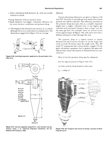
Figure 4-41. Cyclone separator proportions-dust systems. By per-
mission. Perry, J. H., Chemical Engineers Handbook, 3rd Ed., Figure 4-42. Van Tongeran dust shave-off design. Courtesy of Buell
McGraw-Hill Company, 1950. Engineering Co.