
Page 294 - APPLIED PROCESS DESIGN FOR CHEMICAL AND PETROCHEMICAL PLANTS, Volume 1, 3rd Edition
P. 294
266 Applied Process Design for Chemical and Petrochemical Plants
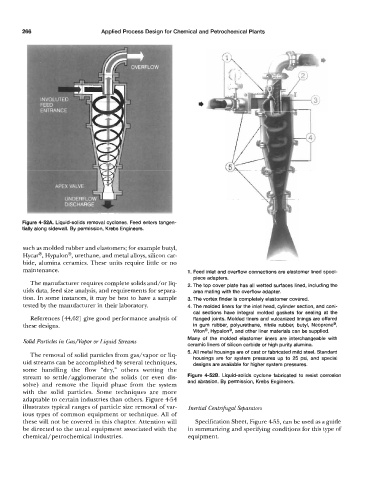
Figure 4-52A. Liquid-solids removal cyclones. Feed enters tangen-
tially along sidewall. By permission, Krebs Engineers.
such as molded rubber and elastomers; for example butyl,
Hycar@, Hypalon@, urethane, and metal alloys, silicon car-
bide, alumina ceramics. These units require little or no
maintenance. 1. Feed inlet and overflow connections are elastomer lined spool-
piece adapters.
The manufacturer requires complete solids and/or liq- 2. The top cover plate has all wetted surfaces lined, including the
uids data, feed size analysis, and requirements for separa- area mating with the overflow adapter.
tion. In some instances, it may be best to have a sample 3. The vortex finder is completely elastomer covered.
tested by the manufacturer in their laboratory. 4. The molded liners for the inlet head, cylinder section, and coni-
cal sections have integral molded gaskets for sealing at the
References [ 44,621 give good performance analysis of flanged joints. Molded liners and vulcanized linings are offered
these designs. in gum rubber, polyurethane, nitrile rubber, butyl, Neoprene@,
Viton@, Hypalon@, and other liner materials can be supplied.
Solid Particles in Gasmapor or Liquid Streams Many of the molded elastomer liners are interchangeable with
ceramic liners of silicon carbide or high purity alumina.
5. All metal housings are of cast or fabricated mild steel. Standard
The removal of solid particles from gas/vapor or liq-
uid streams can be accomplished by several techniques, housings are for system pressures up to 25 psi, and special
designs are available for higher system pressures.
some handling the flow “dry,” others wetting the
stream to settle/agglomerate the solids (or even dis- Figure 4-528. Liquid-solids cyclone fabricated to resist corrosion
solve) and remove the liquid phase from the system and abrasion. By permission, Krebs Engineers.
with the solid particles. Some techniques are more
adaptable to certain industries than others. Figure 4-54
illustrates typical ranges of particle size removal of var- Inertial Centrifugal Separators
ious types of common equipment or technique. All of
these will not be covered in this chapter. Attention will Specification Sheet, Figure 455, can be used as a guide
be directed to the usual equipment associated with the in summarizing and specifying conditions for this type of
chemical/petrochemical industries. equipment.