Page 291 - APPLIED PROCESS DESIGN FOR CHEMICAL AND PETROCHEMICAL PLANTS, Volume 1, 3rd Edition
P. 291

Mechanical Separations                                     263

              If inlet vane is formed with inlet connection:                                     -             ___
                                                                     Areas:                 Gas Velocity  Velocity Head"
                                                                 Inlet duct:      1.398 sq ft   47.7 ft/sec   0.50 in. water
              K = 7.5
                                                                 Cyclone inlet:   2.0 sq ft   33.33 ft/sec  0.25 in. water
                                                                 Cyclone exit duct:   3.14 sq ft   21.2 B/sec   0.10 in. water
           Example 4-6: Cyclone System Pressure Drop             ~.                             .. .~             -
                                                                 *Velocity head, inches water = Voz/ (16) ( lo6), Ti, = ft/min

              A cyclone system is to be installed as a part of a bagging   Friction Loss  @  to  @  :
            operation. The unit is  shown in Figure 448. Determine
            the head required €or purchase of the fan. The conditions      N,,   2 398,000       f  = 0.Q038
            are:
              Air volume: 4000 cu ft per min of air at 70°F                      4fL
                                                                    No. Vel.  Hd.  = -   (.0038) ('*I   = 0.204vel.  head
                                                                                     =
              Air density: 0.075 lb/cu  ft                                        D       (16/12)


                          100

                           90
                           ao

                           70
                           60
                           50

                           40
                           30
                           20

                           10
                           0
                             63    5       10     15     20      25     30     35      40     45      50
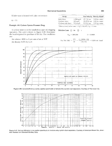
                   ure 4-46. General efficiency cwves, applies specifically to helical entry cyclone dust separators. Courtesy of The Ducon Co.


                                              TERMINAL   VELOCITY  -  INCHES  PER  MINUTE
           Figure 4-47. General efficiency cuwe applies specifically to involute entry cyclone dust separators. Courtesy of American
           ican Radiator and Standard Sanitary Corp.
   286   287   288   289   290   291   292   293   294   295   296