
Page 275 - APPLIED PROCESS DESIGN FOR CHEMICAL AND PETROCHEMICAL PLANTS, Volume 1, 3rd Edition
P. 275
Mechanical Separations 247
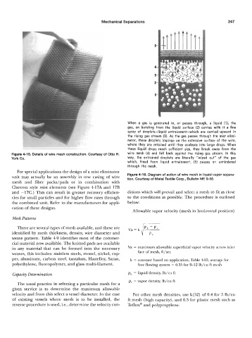
When a gas is generated in, or passes through, a liquid (11, the
gas, on bursting from the liquid surface (2) carries with it a fine
spray of droplets-liquid entrainment-which are carried upward in
the rising gas stream (3). As the gas passes through the mist elimi-
nator, these droplets impinge on the extensive surface of the wire,
where they are retained until they coalesce into large drops. When
thess liquid drops reach sufficient size, they break away from the
Figure 4-15. Details of wire mesh construction. Courtesy of Otto H. wire mesh (4) and fall back against the rising gas stream. In this
York co. way, the entrained droplets are literally "wiped out" of the gas
which, freed from liquid entrainment, (5) passes on unhindered
through the mesh.
For special applications the design of a mist eliminator
unit may actually be an assembly in one casing of wire Figure 4-16. Diagram of action of wire mesh in liquid-vapor separa-
tion. Courtesy of Metal Textile Corp., Bulletin ME 9-58.
mesh and fiber packs/pads or in combination with
Chevron style mist elements (see Figure 417A and 17B
and -17C.) This can result in greater recovery efficien- ditions which will prevail and select a mesh to fit as close
cies for small particles and for higher flow rates through to the conditions as possible. The procedure is outlined
the combined unit. Refer to the manufacturers for appli- below:
cation of these designs.
Allowable vapor velocity (mesh in horizontal position)
Mesh Patterns
There are several types of mesh available, and these are Va= k
identified by mesh thickness, density, wire diameter and i i"
weave pattern. Table 49 identifies most of the commer-
cial material now available. The knitted pads are available
in any material that can be formed into the necessary Va = maximum allowable superficial vapor velocity across inlet
weaves, this includes: stainless steels, monel, nickel, cop- face of mesh, ft/sec
per, aluminum, carbon steel, tantalum, Hastelloy, Saran, k = constant based on application, Table 410, average for
polyethylene, fluoropolymer, and glass multi-filament. free flowing system = 0.35 for 9-12 lb/cu ft mesh
Capacity Determination pL = liquid density, lb/cu ft
pv = vapor density, lb/cu ft
The usual practice in selecting a particular mesh for a
given service is to determine the maximum allowable
velocity and from this select a vessel diameter. In the case For other mesh densities, use k(52) of 0.4 for 5 lb/cu
of existing vessels where mesh is to be installed, the ft mesh (high capacity), and 0.3 for plastic mesh such as
reverse procedure is used, i.e., determine the velocity con- Teflon@ and polypropylene.