Page 90 - APPLIED PROCESS DESIGN FOR CHEMICAL AND PETROCHEMICAL PLANTS, Volume 1, 3rd Edition
P. 90

76                        Applied Process Design for Chemical and Petrochemical Plants

             (table continuedfrom previous pagej
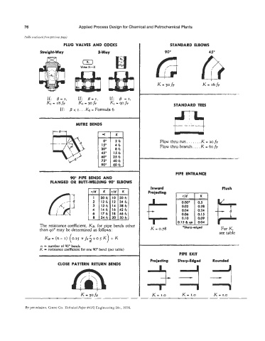
                               PLUG VALVES  AND  COCKS                           STANDARD  ELBOWS

                    Straight-Way               3-Way                          90"                  45"
                                        0
                                       View X-X


                       If:  /? = I,   If:  6 = I,   If:  0 = I,
                       Ki =  18fT     Ki - 3OfT      Ki  = WfT                    STANDARD TEES
                             If:  0 < I. . . Kz = Formula 6


                                     MITRE  BENDS                                 kmd
                                                                                       .- . a
                          tcdl

                                                                            Flow thru run. . . . . . . K - 20 fT
                                                                            Flow thru branch. . . . K = 60 fT
                                                      15 fr
                                                      25 fr
                                 Vd


                                                                                   PIPE  ENTRANCE
                                  90" PIPE  BENDS  AND
                                                                      c
                         FLANGED  OR  BUTT-WELDING 90" ELBOWS           Inward                           Flush

                                                                      Projecting


                                                12fr  14  386
                                            4   14fr  16  42fr
                                                17fr  18  46f1                        0.06
                                             8   24 fr  20  50 fr
                    The resistance coefficient, KD, for pipe bends other   K   =  0.78
                                                                                                        For K,
                    than 90'  may be determined as follows:                            *Sharp-edged     see table
                                           r
                      KB = (n- I)  (0.25  ?r fi;i+o.5  K
                    n  = number of 90" bends
                    K  = resistance coefficient for one 90' bend (per table)
                                                                                     PIPE  EXIT
                                                                       Proiecting   Sharp-Edged      Rounded
                            CLOSE  PATTERN RETURN BENDS


                                                                        K - 1.0       K - 1.0        K - 1.0

             By permission,  Crane Co. Technical Paper #410, Engineering Div., 1976.
   85   86   87   88   89   90   91   92   93   94   95