
Page 92 - APPLIED PROCESS DESIGN FOR CHEMICAL AND PETROCHEMICAL PLANTS, Volume 1, 3rd Edition
P. 92
78 Applied Process Design for Chemical and Petrochemical Plants
Reynolds number and the friction factor for all conditions
of flow using the appropriate f and K values.
K = f (L/D) (2-25)
hf = K(v~ - ~2)'/2g (2-31)
and:
hf = (f L/D) (v2/2g), ft fluid for pipe (2-26)
hf = (K) (v2/2g), ft fluid for valves and fittings (2-27)
1TH J AP/lOO eq. ft* = 0.0668 (pv/d2) = 0.0273 pLQ/d4,
psi/lOO eq. ft (2-32)
-.-
0 I 2 3 4 5 6 7 8 9 IO AP = (AP/lOO) (Leq), psi (2-33)
3-
D
D *Equivalent feet of straight pipe; i.e., straight pipe plus
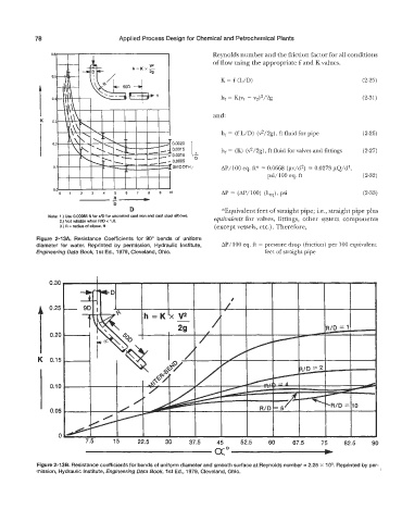
Note: 1 .) Use 0.00085 fi for FJD for uncoated cast iron and cast steel elbows.
2.) Not reliable when WD c 1 .O. equivalents for valves, fittings, other system components
3.) R = radius of elbow, fl (except vessels, etc.) . Therefore,
Figure 2-13A. Resistance Coefficients for 90" bends of uniform
diameter for water. Reprinted by permission, Hydraulic Institute, AP/lOO eq. ft = pressure drop (friction) per 100 equivalent
Engineering Data Book, 1 st Ed., 1979, Cleveland, Ohio. feet of straight pipe
Figure 2-13B. Resistance coefficients for bends of uniform diameter and smooth surface at Reynolds number = 2.25 x lo5. Reprinted by per-
mission, Hydraulic Institute, Engineering Data Book, 1st Ed., 1979, Cleveland, Ohio.