
Page 98 - APPLIED PROCESS DESIGN FOR CHEMICAL AND PETROCHEMICAL PLANTS, Volume 1, 3rd Edition
P. 98
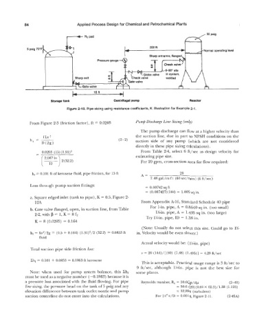
84                       Applied Process Design for Chemical and Petrochemical Plants

                                                                                                     30 psig
                                 I-+                                                      d
                                 I        N2pad                                           1       I
              5  psig 70’F-l                                              200 ft                    Noi  mal operating level


                                                Pressure gauge


                                                     c T
                                     Sharp exit      a


                                              15R
                          Storage tank                  Centrifugal pump                     Reactor
                                  Figure 2-19. Pipe sizing using resistance coefficients, K. Illustration for Example 2-1.


                From Figure 2-3  (friction factor), ft = 0.0205    Pump Discharge Line Sizing (only)
                                                                     The pump discharge can flow at a higher velocity than
                                                                   the suction line, due in part to NPSH conditions on the
                                                           (2- 2)   suction  side  of  any  pump  (which  are  not  considered
                                                                   directly in these pipe sizing calculations).
                     (T)                                           estimating pipe size.
                   -  0.0205  (15) (l.91)z                           From Table  2-4, select 6 ft/sec  as  design velocity for
                               2(32.2)
                                                                     For 20 gpm, cross-section area for flow required:

                 hf = 0.101 ft of kerosene fluid, pipe friction, for 15 ft   A=         20
                                                                          7.48 gal/cu  f t  (60 sec/min  ) (6 ft/sec)
                Loss through pump suction fittings:                     = 0.00742 sq ft
                                                                        = (0.007427)(144) = 1.009 sq in.
                a. Square edged inlet (tank to pipe), K = 0.5, Figure 2-
                  12A                                                From Appendix A-16, Standard Schedule 40 pipe
                                                                          For 1-in. pipe, A = 0.8640 sq in. (too small)
                b. Gate valve flanged, open, in suction line, from Table     1%-in. pipe, A = 1.495 sq in. (too large)
                  2-2, With p = 1, K = 8 fT
                                                                        Try 1X-h pipe, ID = 1.38 in.
                  K = 8 (0.0205) = 0.164
                                                                      (Note: Usually do not select this size. Could go to 1%-
                hf = Kvz/2g  = (0.5 f 0.164)  (1.91)2/2 (32.2) = 0.0853 ft   in. Velocity would be even slower.)
                    fluid
                                                                      Actual velocity would be: (1Kin. pipe)
                Total suction pipe side friction loss:
                                                                      v = 20  (144)/[(60)  (7.48)  (1.495)] = 4.29 ft/sec
                Ch, = 0.101 + 0.0853 = 0.1863 ft kerosene
                                                                      This is acceptable. Practical usage range is 3 ft/sec  to
                                                                   9  ft/sec,  although  lg-in. pipe  is  not  the  best  size  for
                Note:  when  used  for  pump  system  balance,  this  Xhf   some plants.
             must be used as a negative number (-0.1863)  because it is
             a pressure loss associated with the fluid flowing. For pipe   Reynolds number, R,  = 50.6Qp/dp     (2-49)
              line sizing, the pressure head on the tank of 5 psig and any             = 50.6 (20) (0.81 X  62.3)/1.38  (1.125)
             elevation difference between tank outlet nozzle and pump                  = 32,894 (turbulent)
              suction centerline do not enter into the calculations.         For 1%’’ &/D = 0.0014, Figure 2-11.   (2-49A)