
Page 177 - Applied Process Design For Chemical And Petrochemical Plants Volume II
P. 177
166 Applied Process Design for Chei nical and Petrochemical Plants
Cv
7 , VAPOR LOAD CORRECTION FACTOR In any case, the average head over the cap slots for the
1.4 section should approximately equal the average head over
the adjoining sections, and the inlet and outlets of the sec-
1.3
tion should not be extreme, even though the average is
acceptable. The object of fairly uniform head over the
1.2
slots should be kept in mind when reviewing the gradient
I. I adjustments.
1.0 Riser and Reversal Pressure Drop
0.9 The method proposed by Bolles fits the average design
problem quite satisfactorily. However, for low pressure
0.8
drop designs as in vacuum towers, it may well require
0.7 checking by the more detailed method of Dauphine [ 131.
0.6 A. Bolks ' Design Method [51:
0.5 Solve for the combined riser, reversal, annulus, and slot
pressure drop by:
OS40 IO 20 30 40 50 60 70 80 90 100
LIQUID LOAD PER FOOT MEAN TRAY WIDTH,GPM
(8 - 231)
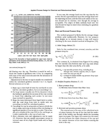
Figure 8-113. Correction of liquid gradient for vapor load. Used by
permission, 0 The American Chemical Society, Davies, J. A., Ind. and The constant, &, is obtained from Figure 8-114, noting
Eng. Chem, V. 39, (1947) p. 774.
that the annular area between riser and cap must always
be larger than the riser area for I& to be valid.
(text continuedjknnpage 161)
where h,, = cap assembly pressure drop, including drop
uid flowing over the cap. Therefore it would be well to through riser, reversal, annulus, slots, in. liquid
check the results of gradients over 1.0 in. by comparing Ar = total riser area per tray, ft2
with some of the other methods and with the tabulation of I& = constant for Bolles bubble cap pressure drop equa-
data of Reference 38. tion, Figure 8-114
Adjustments to the tray or caps is usually not considered
unless the calculated gradient exceeds % to 1 in. liquid. B. Modijied Dauphine Relations 15, 1 I]:
Several schemes are in use:
1. Riser pressure drop
1. Raise cap in inlet half of tower by onefourth to one (1) Reversal Area Greater than Riser Area
half the calculated gradient, but not exceeding 1 in.
2. For large towers (usually over 8 ft in diameter) check (8 - 232)
the hydraulic gradient for sections of the tray normal
to liquid flow, adjusting each section by not more
than onehalf the gradient. (2) Reversal Area Less than Riser Area
3. Slope the trays downward from liquid inlet to outlet,
with the total drop from inlet to outlet weir not d
(pr)v2
exceeding one-half the calculated gradient. h, = 0.099J(ar/ar,)1'2 [ (Ar)r (8-233)
4. Cascading the tray by using weirs as dams to divide the PL
tray in steps, each step or section of the tray having no 2. Reversal and annulus pressure drop
significant gradient from its inlet to outlet. This is usu- The reversal area is the area of the cylindrical verti-
ally only considered for trays 10 ft in dia. and larger, as cal plane between the top of the riser and the under-
it adds considerably to the cost of each tray. side of the bubble cap through which the incoming
5. More elaborate tests and adjustments can be made vapor must pass. The vapor then moves into the annu-
[5]. However, they are usually unnecessary except in lus area between the inside diameter of the cap and
unusual cases of very high liquid loads and/or large the outside diameter of the riser before entering the
columns. slots in the cap.