
Page 231 - Applied Process Design For Chemical And Petrochemical Plants Volume II
P. 231
220 Applied Process Design for Chemical and Petrochemical Plants
Sheet 1 of 2 Sheet 2 of 2
TRAY DATA SHEET TRAY DATA SHEET
Plant Location - Engineer - Item No. Sewlce
Client
Job No. Inquiry No. Date Section (NamelDescription)
Item No. Sewlce Tray Numbers Included
PERFORMANCE REQUIREMENTS:
Tray No. 1 = ToplBtm Max. AP per Tray,
mmHg (mbar) ----
Section (Name/Descrlption) _.--- Max. % Jet Flood ----
Tray Numbers Included ---- Max. DC Liq. Velocity, mls ----
_---
Loading at Actual Tray No. ---- Max. DC Backup, ----
Number of Trays Requlred Clear Liq., mm ----
Derating Factor
NORMAL VAPOR TO: Purpose for Derating ----
Weight Rate, kgBi ____-- (Foaming, System, Safety)
Density, kg/ms ---- MECHANICAL REQUIREMENTS
Volume Rate, Actual m3/s ---- Tower lnslde Diameter, mm
Number of Passes
Molecular Weight ---- Tray Spacing, mm
Viscosity, mPa-s ---- Type of Tray
Pressure, kPa (bar a) ---- HolelB Cap Diameter, mm
Temperature, 'C ---- Deck Materialfrhickness, mm
ValvelB Cap Material
Design Range, Oh of Normal ---- Hardware Material
Support MaterialTThlckness, mm
NORMAL LIQUID FROM: Total Corrosion Allowance, mm
Welght Rate, kglh ---- Vessel Manhole I.D., mm
Density, kglms ---- MISCELLANEOUS
Volume Rate, Actual ma/s __--- Solids Present: Yes / No Flashing Feed Yes / No
Molecular Weight ---- Anti-Jump Baffles: Yes I No I Vendor Preference
Recessed Seal Pans: Ye$ I No I Vendor Preference
Surface Tension, mNIm ---- Specify Equal Bubbling Areas / Flow Path Lengths per pass
Viscosity, mPa-s ---- Deslgn Load:
Temperature, 'C _.--- -kPa (mbar) with - mm deflection at -C. or
Design Range, YO of Normal ____-- Standard: 1.4 kPa with 3 mm at 150' C.
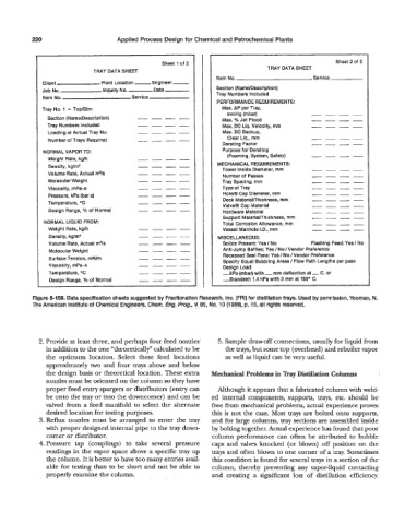
Figure 8-159. Data specification sheets suggested by Fractionation Research, Inc. (FRI) for distillation trays. Used by permission, Yeoman, N.
The American Institute of Chemical Engineers, Chem. Eng. Prog, V. 85, No. 10 (1989), p. 15, all rights reserved.
2. Provide at least three, and perhaps four feed nozzles 5. Sample draw-off connections, usually for liquid fiom
in addition to the one "theoretically" calculated to be the trays, but some top (overhead) and reboiler vapor
the optimum location. Select these feed locations as well as liquid can be very useful.
approximately two and four trays above and below
the design basis or theoretical location. These extra Mechanical Problems in Tray Didlation Columns
nozzles must be oriented on the column so they have
proper feed entry spargers or distributors (entry can Although it appears that a fabricated column with weld-
be onto the tray or into the downcomer) and can be ed internal components, supports, trays, etc. should be
valved from a feed manifold to select the alternate free from mechanical problems, actual experience proves
desired location for testing purposes. this is not the case. Most trays are bolted onto supports,
3. Reflux nozzles must be arranged to enter the tray and for large columns, tray sections are assembled inside
with proper designed internal pipe to the tray down- by bolting together. Actual experience has found that poor
comer or distributor. column performance can often be attributed to bubble
4. Pressure tap (couplings) to take several pressure caps and valves knocked (or blown) off position on the
readings in the vapor space above a specific tray up trays and often blown to one comer of a tray. Sometimes
the column. It is better to have too many entries avail- thii condition is found for several trays in a section of the
able for testing than to be short and not be able to column, thereby preventing any vapor-liquid contacting
properly examine the column. and creating a significant loss of distillation efficiency.