Page 241 - Applied Process Design For Chemical And Petrochemical Plants Volume II
P. 241

Chapter


                                            Packed Towers


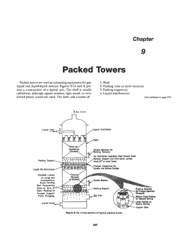
              Packed towers are used as contacting equipment for gas-   1. Shell
            liquid and liquid-liquid systems. Figures 9-1A and B pre-   2.  Packing (one or more sections)
            sent a cross-section of a typical unit. The shell is usually   3. Packing support(s)
            cylindrical, although square wooden, light metal, or rein-   4. Liquid distributor(s)
            forced plastic towers are used. The basic unit consists of:                            (text continwd on page 234)


                                                   t Gas  Outlet


                              Liquid %                          Liquid  Distributor


                                                                 Shell


                                                Khmped or        Access Monwoy for
                                           1  ,Stocked),   L,../Packing   Removal
                                                           I
                                                       \ IY      I",  ",..,,..........  ..*-.-  ..-..   -..-- --
                                                                 car  nictillntinn  nnnmtinn Faed  Shnuld Enter
                                                                 Between Support  and  Distributor ,unless
                           Packing  Support                      Smoll(12"or less) Tower.
                                                                 Flanged  Connection for
                        Liquid  Re-Distributor                   Access  into Bottom Section
                           Stacked  Layers

                             Intermediate
                          (Not  Necessarily
                          Same  as  Bulk  of             &Pocking     Support
                          Tower  Packing) to
                          Prevent  Support
                           Plate  Plugging.


                                              Figure 9-1 A.  Cross-section of typical packed tower.


                                                                230
   236   237   238   239   240   241   242   243   244   245   246