
Page 245 - Applied Process Design For Chemical And Petrochemical Plants Volume II
P. 245
234 Applied Process Design for Chemical and Petrochemical Plants
Liquid l n l a T & Vapor Outlet
(lex1 continuedfiom page 230) Cover Section-
5. Intermediate supports and redistributors
6. Gas and liquid entrance and exit nozzles
Intermediate Section
Many of the mechanical aspects of tower construction
and assembly have an influence upon the design and inter-
pretation of tower performance. Every effort should be
made to increase the effectiveness of contact between the Intermediate Section
process streams and to reduce losses by entrainment or With Bottom Rim
wall effects at a minimum expenditure of pressure drop. At
the same time the design must be consistent with the ece
nomics dictated by the process and type of construction. Intermediate Section
Shell
The shell may be of metal (steel, alloy, or non-ferrous),
plastic, wood or some combination which may require the
addition of liners or inner layers of rubber, plastic or
brick. The mechanical problems of attaching inner noz-
zles, supports and brick require considerable attention id Outlet
that is not an integral part of sizing the equipment. Fig-
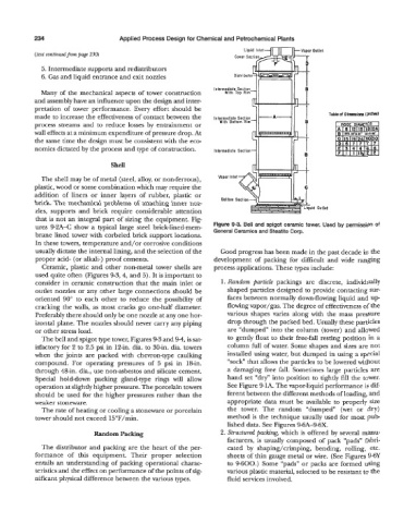
ures 9-2A-C show a typical large steel brick-lined-mem- Figure 9-3. Bell and spigot ceramic tower. Used by permission of
General Ceramics and Steatite Corp.
brane lined tower with corbeled brick support locations.
In these towers, temperature and/or corrosive conditions
usually dictate the internal lining, and the selection of the Good progress has been made in the past decade in the
proper acid- (or alkali-) proof cements. development of packing for difficult and wide ranging
Ceramic, plastic and other non-metal tower shells are process applications. These types include:
used quite often (Figures 9-3, 4, and 3). It is important to
consider in ceramic construction that the main inlet or 1. Random particle packings are discrete, individually
outlet nozzles or any other large connections should be shaped particles designed to provide contacting sur-
oriented 90” to each other to reduce the possibility of faces between normally down-flowing liquid and up
cracking the walls, as most cracks go one-half diameter. flowing vapor/gas. The degree of effectiveness of the
Preferably there should only be one nozzle at any one hor- various shapes varies along with the mass pressure
izontal plane. The nozzles should never carry any piping drop through the packed bed. Usually these particles
or other stress load. are “dumped” into the column (tower) and allowed
The bell and spigot type tower, Figures 9-3 and 9-4, is sat- to gently float to their free-fall resting position in a
isfactory for 2 to 2.5 psi in 12-in. dia. to 30-in. dia. towers column full of water. Some shapes and sizes are not
when the joints are packed with chevron-type caulking installed using water, but dumped in using a special
compound. For operating pressures of 5 psi in 18-in. “sock” that allows the particles to be lowered without
through 48-in. dia., use non-asbestos and silicate cement. a damaging free fall. Sometimes large particles are
Special hold-down packing gland-type rings will allow hand set “dry” into position to tightly fill the tower.
operation at slightly higher pressure. The porcelain towers See Figure 9-1A. The vapor-liquid performance is dif-
should be used for the higher pressures rather than the ferent between the different methods of loading, and
weaker stoneware. appropriate data must be available to properly size
.
-
The rate of heating or cooling a stoneware or porcelain the tower. The random “dumped” (wet or dry)
tower should not exceed 15”F/min. method is the technique usually used for most pub
lished data. See Figures 9-6A-9-6X.
Random Packing 2. Structured packing, which is offered by several manu-
facturers, is usually composed of pack “pads” fabri-
The distributor and packing are the heart of the per- cated by shaping/crimping, bending, rolling, etc.
formance of this equipment. Their proper selection sheets of thin gauge metal or wire. (See Figures 9-6y
entails an understanding of packing operational charac- to 9-600.) Some “pads” or packs are formed using
teristics and the effect on performance of the points of sig- various plastic material, selected to be resistant to the
nificant physical difference between the various types. fluid services involved.