Page 246 - Applied Process Design For Chemical And Petrochemical Plants Volume II
P. 246

Packed Towers                                          235


                                                                                           Tower
                                                                                           Cover,
                                  -                                                        Distribu-
                         DIMENSIONS OF STANDARD TOWERS                                     Fig. 360
                    Inside                                                                 tor,
                  Diameter of   24 in.   30 in.   36 in.   40 in.   48 in.   60 in.        Fig. 401
                   Tower A        -                                                        (See op-
                                       -
                  -I
                                                                                           posite
                     A      24    30    36
                     A'     23%   29%   35                                                 page)
                     B      27%   34    41%
                      C     36    36    36                                                 Tower
                      C'    30    30    36                                                 Section
                      D            6    6                                                  with
                      E           15    15                                                 Rim for
                      F           12    14
                      G            8    12                                                 Dis tribu-
                     H       8    1;s   I;%                                                tor,
                      I      3%                                                            Fig. 356b
                             I
                      i            2%   2%    4     4     4
                                        4
                                   4
                      M      3     3    3
                      0      7     93.6  11?4
                      P      3     3    3
                                   8    11
                                   1%  ;2                         R                        Pia in
                                   1%
                                                                                           Tower
                                    %
                                  - -                                                      See tion
                                        1
                   S is inside diameter of ground in faucet.                               Fig. 356
                                 WEIGHTS
                                                                 R
                                                                                           Tower
                                       - -  -                                             Section
                                                        -
                                          Diameter
                                                                                          with Rim
                            - -              40 in.   48 in.   -                          atBottom
                            24 in.
                                       -  -  -
                                  30 in.
                                                        60 in.
                                       36 in.
                  Tower Cover.                                                            Fig. 356a
                  Pi. 360
                  Weight, Ibs.   80   130   215   300   SO0   700
                  Tower                                                                   Support-
                  Distributor,                                                            ing Plate
                  Fig. 401 and                                                            Fig. 279*
                  401.
                  Weight, Ibs.   36   60   100   I20   I 70   250
                 Plain Tower
                 section,
                 Fig.  356
                 Weight, Ibr.   220   300   430   520   700   1000                         Tower
                                                                                           Section
                 Tower Sectior
                 with Rim                                                                  with
                 Fig. 356.  and                                                            Branch,
                 356b                                                                      Fig. 355
                 Weight, Ibs.   225   310   445   540   7%   1100
                 Supporting
                 Plate, Fig. 275
                 Weight. Ibs.   30   80   140   160   250   400                           Tower**
                                                                                          Saucer
                 Tower Section                                                            Fig. 354
                 with branch,
                 Fig. 355
                 Weight.  Ibs.   230   320   530   630   900   1800
                 Tower sauccr,
                 Fig. 354
                 Weight, Ibs.   120   200   2 50   340   S00   800
                 rMBottm
                 Seetion.
                 ?ig. 35511
                 Height, Ib.   260   370   610   730   1000   1500
                                                        -
                                            -  -
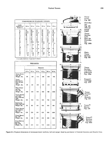
       Figure 9-4. Physical dimensions of stoneware tower sections, bell and spigot. Used by permission of General Ceramics and Steatite Corp.
   241   242   243   244   245   246   247   248   249   250   251