
Page 247 - Applied Process Design For Chemical And Petrochemical Plants Volume II
P. 247
236 Applied Process Design for Chemical and Petrochemical Plants
LlWlD Nrn PIPE 3. Grid packing is probably the newest type packing. It is
lower in pressure drop, and has higher capacity, and
lower efficiency than the other types. (See Figures 9-
LAT 'RlNG
6PP-9-6UU.)
The types and corresponding physical data for packing
are given in Figure(s) 9-6 and Tables 9-1 through 9-15.
The evaluation of these materials for various conditions of
service is given later. However, Table 9-16 outlines packing
service applications and Table 9-17 summarizes usual
packing type applications.
F=l -BANDS Packing Supports
ANGLEWNC The packing support may be anything from cross-grid
bars spaced to prevent fall-through of packing to more
RIM
refined speciality units designed to direct the flow of gas
and liquid. (See Figures 9-7A-9-7F.) Good tower perfor-
manceis definitely linked to proper packing support. The
net free flow cross-sectional area of the support should be
65% (or larger) of the tower area, and greater than the
free area of the packing itself. In addition, the effect of the
free area "blocking" by the positioning of the packing on
the support must be considered. To allow for this, every
effort should be made to obtain as large a support-free
area as possible and yet remain consistent with the struc-
tural strength of the material being used. If this area is too
restricted, liquid build-up will occur at the plate, reducing
efficiency and increasing pressure drop of the tower, and
leading to a flooding condition. A lot depends on the
material of construction that the system requires; for
example, carbon or graphite bar grids, brick grid piers,
some steel grating grids and most rubber or plastic cov-
Maz. Wd6 sup Joint for s.ctbn Toann
Size O.D. Height BotIom I *b Rlns I -Let I
cknemsE'-
of
-
-
- Section eT.1B.T. 1.D.xTk. A IB hh'k.1 Sire I ID. I B.C. 1 ID. l0.D. INo.
-
-
-
12' 12% 154L
15" 15% 17%
18" 18% 20% 19%
- 20% 23%
20"
2 24% 26%
2'4" 30% 33 %
36% 39'k
9'
- 42% 45H
3'4"
4 48% 51H 48% 48%
80% 63% 58% 61%
5 73 76% 70% 74 46
6
- -
-
85% 89% 82% 86%
7
8 87% 100% 94% 98%
- 1% 1% ...... 9 8 2 5 x5 XH 108% 112% 108% 110% 72
9 110% 12'4'
- -
118% 12241 115% 120
10 120 12'4"
1% 1% ...... 9 a 2% 5 x5 .%
u1dlmeadonrosininch..~as othemimnoled.
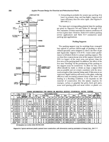
Figure 9-5. Typical reinforced plastic packed tower construction; with dimensions used by permission of Havsg Corp., Bull. F-7.