
Page 254 - Applied Process Design For Chemical And Petrochemical Plants Volume II
P. 254
Packed Towers 243
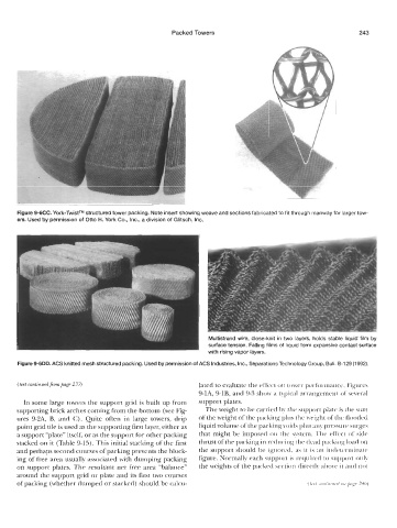
Figure 9-6CC. York-TwistTM structured tower packing. Note insert showing weave and sections fabricated to fit through manway for larger tow-
ers. Used by permission of Otto H. York Co., Inc., a division of Glitsch, Inc.
Multistrand wire, close-knit in two layers, holds stable liquid film by
surface tension. Falling films of liquid form expansive contact surface
with rising vapor layers.
Figure 9-6DD. ACS knitted mesh structured packing. Used by permission of ACS Industries, Inc., Separations Technology Group, Bull. 6-1 29 (1 992).
(text contznwd from prig? 2?7) lated to evaluate the effect oii to\ver performarice. Figures
9-1A, 9-1B, and 9-3 show a typical arrangement of several
In some large towers the support grid is built up from support plates.
supporting brick arches coming from the bottom (see Fig- The weight to he carried the support platt. is the sum
ures 9-2A, B, and C). Quite often in large towers, drip of the weight of the packiiig plus the iveiglit of thc flooded
point grid tile is used as the supporting first layer, either as liquid volume of the packing loitls plus prrsstire surgcs
a support “plate” itself, or as the support for other packing that might be imposed on the sytcni. Tlic effect of side
stacked on it (Table 9-15). This initial stacking of the first thrust of the packing in rediiring the cleat1 packing load on
and perhaps second courses of packing prevents the block- the support should be ignored, as it is iiii intlrtermiiiate
ing of free area usually associated with dumping packing figure. Normally each support is required to support only
on support plates. The resultant net free area “balance” the weights ofthe packcd section directly above it ant1 not
around the support grid or plate and its first two courses
of packing (whether dumped or stacked) should be calcu-