
Page 340 - Applied Process Design For Chemical And Petrochemical Plants Volume II
P. 340
Packed Towers 329
3.0 3.0 3.0
20 2.0 2.0
1 .o 1.0 1.0
0.8 Pd 0.8
Ob Oh 0.4
. . 5 0.4
0.4
0.4
~
~
e 0.3 e 0.3 6 0.3
B 3
.- e r -
% O.* % O2
0.1 0.1 0.1
0.08 01 OM
0.65 om om
0.04 01)1 0.01
om 0.03 0.03
0.02 0.02 0.02
0.4 0.4 0.8 1.0 2.0 3.0 4.0 5.0 0.4 0.4 0.8 1.0 2.0 3ll 4.0 5.0 0.4 Ob 0.8 1.0 2.0 3.0 4.0 5.0
F, fps, Ubm/fis)b Fss fPS (Ibrn/R?’ F,, fps, (lb./fl95
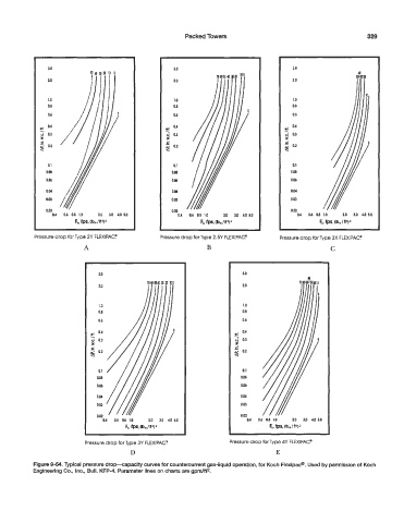
Pressure drop for Type 2Y FLEXIPAC! Pressure drop for Type 2.5Y FLEXIPAC? Pressure drop for Type 3X FLEXIPAC?
A B c
~
3.0 3.0
2.0
1.0
0.8
0.6
5 0.4
0.3
B
-
e
% O2
0.1
0.M
0.06
OY
0.03
0.02
0.4 0.6 0.8 ID 20 3.0 4 5.0 0 6 0.1) 1.0 2.0 3.0 4.0
Fs, fPS Qbrn/Ra)’
Pressure drop for Type 3Y FLEXIPAC? Pressure drop for Type 4Y FLEXIPAC?
D E
Figure 9-54. Typical pressure drop-capacity curves for countercurrent gas-liquid operation, for Koch Flexipac”. Used by permission of Koch
Engineering Co., Inc., Bull. KFP-4. Parameter lines on charts are gpm/ft2.