
Page 333 - Applied Process Design for Chemical and Petrochemical Plants Volume I
P. 333
304 Applied Process Design for Chemical and Petrochemical Plants
Diameter, D = (5 - 33)
Where using consistent units:
P = impeller power draw, F L/t or MLz/t3
t = time
L = length
F = fluid force on turbine, perpendicular to shaft, ML/t‘
D = impeller diameter, L
Q = volumetric flow, L3/t
T = tank diameter, L
p = fluid density, M/L3
p = fluid viscosity, M/ (Lt)
z = torque, FL, or ML2/t2
Z = liquid depth
Rotio of Tonk Diamtt~rllmprlltr Diomcttr N, = power number, dimensionless,
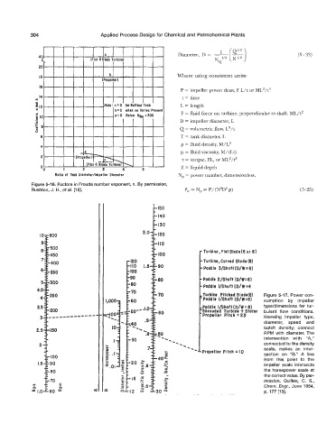
Figure 5-16. Factors in Froude number exponent, n. By permission,
Rushton, J. H., et a/. [18]. Po = N, = P/(N3D5 p) (5-25)
150
140
130
- Turbine, Flat Blade(6 or 8)
100
- Turbine, Curved Blade (6)
-Paddle 3/Shaft(O/W=6)
-Paddle 2/Shoft (O/W=6)
-Paddle I/Shaft (D/W:4
-Turbine Pitched Blodd6) Figure 5-17. Power con-
-Poddie I/Shaft (D/W=61 sumption by impeller
,Paddle VShoft (O/W = 8) type/dimensions for tur-
:Shrouded Turbine + Stator bulent flow conditions.
Propeller Pitch = 20 Knowing impeller type,
diameter, speed and
batch density; connect
RPM with diameter. The
intersection with “A,”
connected to the density
scale, makes an inter-
section on “B.” A line
from this point to the
impeller scale intersects
the horsepower scale at
the correct value. By per-
mission, Quillen, C. S.,
Chem. Engr, June 1954,
4 p. 177 [15].