
Page 330 - Applied Process Design for Chemical and Petrochemical Plants Volume I
P. 330
Mixing of Liquids 301
Table 5-1
Ea€fled Cylindrical Tanks
-
M, K3
Viscous Turbulent
Propeller, %blade, pitch = diameter.. I. 41.0 0.32
Propeller, 3-blade, pitch = 2 diameters. . 43.5 1 .oo
70.0 4.50
Turbine, flat blade, 4 blades.. . . . . . . .
e
Turbine, flat blade, 6 blades.. . . . . . . 71.0 6.30
~
I
Turbine, flat blade, 8 blades.. ~. . . . . . 72.0 7.80
Pan turbine, blades at 45", 6 blades. a . . 70.0 1.65
Shrouded turbine, stator sing. . ~ . . . . . 172.5 1.12
Flat paddles, 2 blades (single paddle),
D/W= 4 .l. .. . . .. ~. ..". -..-.. .. 43.0 2.25
Plat paddles, 2 bJades, /w=6 ...... 36.5 1.60
35.0 1.15
Plat paddles, 2 blades, D/W= 8. ~ . . ~
~
Flat paddles, 4 blades, D/w = 6. I . . , . 49.0 2.75
Flat paddles, 6 blades, D/W = 6. ~. . . . 71.0 3.82
*By permission, R. N. Rushton and J., Y. Oldshue, Chem. Eng.
P
Oldshue I291 points out that to identi9 the turbulent
range as beginning at a specific I'dR, may not be exactly
correct, as it actually varies with different impeller
designs. This range may vary from N, G lo3 to NRe E IO5,
so for comm.on use NRe = IO3 is taken as the turbulent
range for all impellers.
For same Iamily d.esign/styles of impellers [ 291, see Fig-
ure 5-12:
P ot N3 (5-12)
P oc N3D5 (5-1 3)
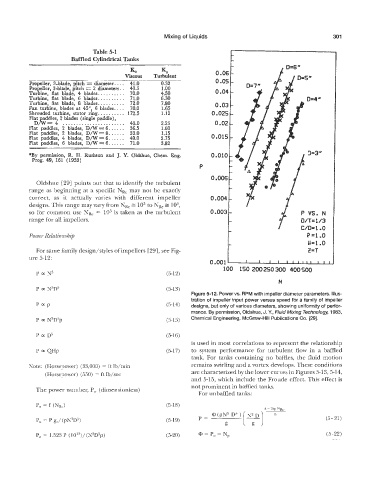
Figure 5-12. Power vs. RPM with impeller diameter parameters. Illus-
tration of impeller input power versus speed for a family of impeller
PEP (5-1 4) designs, but only of various diameters, showing uniformity of perfor-
mance. By permission, Oldshue, J. y., Fluid Mixing TechnologH 1983,
P oc N3D5p (5-15) Chemical Engineering, McGraw-Hill Publicafions CQ. [29].
P oc D5 (5-16)
is used in most correlations to represent the relationship
P QHp (5-17) to system performance for turbulent flow in a baffled
tank. For tanks containing no baffles, the fluid motion
Note: (Horsepower) i(33,OOO) = ft lbimin remains swirling and a vortex develops. These conditions
(Horsepower) 1:550) = ft Ib/sec are characterized by the lower curves in Figures 513,514,
and 5-15, which include the Froude effect. This effect is
not prominent in baffled tanks.
OW~F number, Po (dimensionless)
For unbaffled tanks:
Po = P gJ(pN3DS) (5-19) (5 - 21)
Po = 1.523 P (1013)/(N3D5p) (5-20) @ = Po = N, (3-22)