Page 326 - Applied Process Design for Chemical and Petrochemical Plants Volume I
P. 326

Mixing of Liquids                                       297

                                                            the  system,  in  general  being  a  function  of  viscosity,
                                                            impeller diameter and liquid depth in the tank. In gener-
                                                            al, dual impellers may  be indicated for fluids of  45 cen-
                                                            tipoise and greater and where the fluid travels more than
                                                            four feet before being deflected.
                                                               The circulating  capacity of  %blade square  pitch  pro-
                                                            pellers is theoretically of the magnitude given in Figure 5-
                                                            9. The speed ranges indicated may be grouped as [2] :

                                                               high speed, 1750 rpm:   for  low  viscosity  fluids,
                                                                                       such as water
                                                               medium speed, 1150 rpm:  for medium viscosity fluids,
                                                                                       such  as  light  syrups  and
                                                                                       varnishes
                                                               low speed, 420 rpm:     for  high  viscosity  fluids
                                                                                       such as oils, paints, or for
                                                                                       tender crystals or fibers: or
                                                                                       if foaming is a problem.
                                                               The mixing efficiency is generally higher  (40%-60%)
                                                            for the slow 400 rpm speed and lower (25%-45%) for the
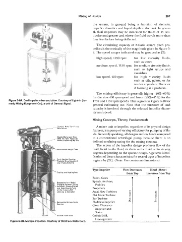
       Figure 5-8A. Dual impeller mixer and drive. Courtesy of Lightnin (for-   1750 and 1150 rpm speeds. This is given in Figure 5-10 for
       merly Mixing Equipment Co.), a unit of General Signal.
                                                            general  estimating  use.  Note  that  the  turnover  of  tank
                                                            capacity is involved through the selected impeller diame-
                                                            ter and speed.

                                                            Mixing Concepts, Theory, Fundamentals

                                                               A mixer unit or impeller, regardless of its physical design
                                                            features, is a pump of varying efficiency for pumping of flu-
                                                            ids. Generally speaking, all designs are low heads compared
                                                            to  a  conventional centrifugal pump, because there  is  no
                                                            defined confining casing for the mixing element.
                                                               The action of the impeller design produces flow of  the
                                                            fluid, head on the fluid, or shear in the fluid, all to varying
                                                            degrees depending on the specific design. Ageneral identi-
                                                            fication of these characteristics for several types of impellers
                                                            is given by  [27]. (Note: Use consistent dimensions).


                                                            Rakes, Gates                              0
                                                            Spirals,  Anchors,
                                                              Paddles
                                                            Propellers
                                                            Axial Flow Turbines     m               m
                                                                                    5
                                                            Flat Blade Turbine      E               3
                                                                                                    z
                                                            Bar Turbine                             E
                                                            Bladeless Impeller     6                Y
                                                            Close Clearance
                                                              Impeller and
                                                              Stator
                                                            Colloid Mill,
       Figui
   321   322   323   324   325   326   327   328   329   330   331