
Page 324 - Applied Process Design for Chemical and Petrochemical Plants Volume I
P. 324
Mixing of Liquids 295
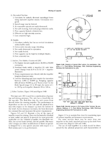
6. Shrouded Turbine 0 = IMPELLER
1. Circulates by radially directed centrifugal force DIAMETER
using enclosed impeller stators. Circulation very
good.
2. Speed range may be limited.
3. At reasonable speeds not easily destroyed.
4. Not self cleaning, fouls and plugs relatively easily.
5. Flow capacity limited, relatively low.
6. Effective in high viscosity systems.
7. Cost: relatively high.
H. Paddle
1. Circulates radially, but has no vertical circulation
unless baffles used. ROTAT ION
2. Covers wide viscosity range, blending.
IMPELLER CENTERLINE (LOCATED
3. Not easily destroyed in operation. AT 1/2 THE BLADE HEIGHT1
4. Not easily faded.
5. Flow capacity can be high €or multiple blades.
6. Cost: relatively low. I
20
T
I. Anchor, Two blades, Contoured [25] .1D
1. For higher viscosity applications: 40,000 to 50,000
centipoise. Figure 5-6A. Drawing of typical lifter turbine. By permission, Old-
2. Nominal blade width is impeller/lO, with little shue, J. Y., Fluid Mixing Technology, 1983, Chemical Engineering
McGraw-Hill Publications Go. [29].
power change from D/8 to D/12 (D = impeller
diameter). 28.0 -
3. Power requirements vary directly with the impeller -
height-to-diameter ratio. 24.0 -
4. Used for blending and heat transfer for viscosities -
between 5,000 eo 50,000 cp. Pumping capacity 20.0-
falls off above 58,000 cp, as it “bores a hole” in the 1
fluid. Speed range 5.5 to 45 mph, for motor of 1 2 16.0 -
e
to 150 hp and impeller diameter 24 to 120 in. N
+ 12.0 -
I -
L9
J. Lifter Turbine, Figure 5-6A and Figure 5-6B CI 8.0 -
-
This type unit 1291 is used for a combination of pump- 4.0 - 4
ing and mixing purposes. The unit has a closed disk on -
the top side. The ked flow into the unit comes from 0.0 L
directly below the rotating impeller. The performance is
dependent on the size of the unit and the physical loca-
tion with respect to the distance up from the bottom of Figure 5-6B. Velocity vectors in R-2 plane (Lifter Turbine). By per-
the vessel. As this clearance increases, the head decreases mission, Oldshue, J. Y., Fluid Mixing Techndogx 1983, Chemical
for constant flow and increases the power requirement. Engineering McGraw-Hill Publications Co. 1291.
Figures 5-3 and 5-5 illustrate a few of the types of
impellers used for mixing. They may be basically classified Figure 5-7 is an analysis flow chart for examining types
as axial, radial and mixed. In general the most generally of turbine impeller performance requirements.
applicable are the %bladed propeller, the flat-blade tur- For some services there may be more than one
bine, the curved blade turbine, and the paddle. The many impeller on the shaft, attached part-way up the shaft from
other designs are either modifications of these or special- the lower one (Figures 5-SA and 5-8B).
ly designed for a very special purpose with respect to a The use of dual impellers on a shaft should be deter-
fluid system and/or its performance. mined by the physical properties and characteristics of