
Page 327 - Applied Process Design for Chemical and Petrochemical Plants Volume I
P. 327
298 Applied Process Design for Chemical and Petrochemical Plants
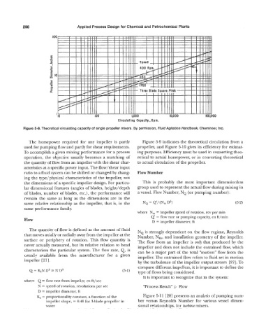
Figure 5-9. Theoretical circulating capacity of single propeller mixers. By permission, Fluid Agitation Handbook, Chemineer, Inc.
The horsepower required for any impeller is partly Figure 5-9 indicates the theoretical circulation from a
used for pumping flow and partly for shear requirements. propeller, and Figure 5-10 gives its efficiency for estimat-
To accomplish a given mixing performance for a process ing purposes. Efficiency must be used in converting theo-
operation, the objective usually becomes a matching of retical to actual horsepower, or in converting theoretical
the quantity of flow from an impeller with the shear char- to actual circulation of the propeller.
acteristics at a specific power input. The flow/shear input
ratio to a fluid system can be shifted or changed by chang- Flow Number
ing the type/physical characteristics of the impeller, not
the dimensions of a specific impeller design. For particu- This is probably the most important dimensionless
lar dimensional features (angles of blades, height/depth group used to represent the actual flow during mixing in
of blades, number of blades, etc.), the performance will a vessel. Flow Number, NQ (or pumping number) :
remain the same as long as the dimensions are in the
same relative relationship as the impeller, that is, in the
same performance family.
where N, = impeller speed of rotation, rev per min
Q’ = flow rate or pumping capacity, cu ft/min
Flow
D = impeller diameter, ft
The quantity of flow is defined as the amount of fluid NQ is strongly dependent on the flow regime, Reynolds
that moves axially or radially away from the impeller at the Number, NRe, and installation geometry of the impeller.
surface or periphery of rotation. This flow quantity is The flow from an impeller is on4 that produced by the
never actually measured, but its relative relation to head impeller and does not include the entrained flow, which
characterizes the particular system. The flow rate, Q, is can be a major part of the total “motion” flow from the
usually available from the manufacturer for a given impeller. The entrained flow refers to fluid set in motion
impeller [21]. by the turbulence of the impeller output stream [27]. To
compare different impellers, it is important to define the
Q = KIN D3 = N D3 (5-1) type of flows being considered.
It is important to recognize that in the system:
where Q = flow rate from impeller, cu ft/sec
N = speed of rotation, revolutions per sec “Process Result” p Flow
D = impeller diameter, ft
Kl = proportionality constant, a function of the Figure 5-1 1 [ 281 presents an analysis of pumping num-
impeller shape, = 0.40 for 3-blade propeller in ber versus Reynolds Number for various vessel dimen-
water sional relationships, for turbine mixers.