
Page 331 - Applied Process Design for Chemical and Petrochemical Plants Volume I
P. 331
302 Applied Process Design for Chemical and Petrochemical Plants
where is read from the charts and the constants a and ever, in the extremities of a vessel, the motion would be
b are given in Figure 5-16. laminar. In this case, as in all others, the tank baffling is a
Figure 5-17 is useful for determination of horsepower major factor for performance of the system and the power
during turbulent flow for various types of impellers, and and flow results.
Figure 5-18 is useful for laminar flow. Also see Figure 5-19. For NRe > 1000, the properly baffled tank is turbulent
Flow and power numbers each decrease as the throughout. NQ and Po are independent of NR~. If the
Reynolds number increases. In unbaffled tanks, a vortex tank is not baffled, a “forced vortex” dominates the flow
forms that takes over the flow regime and does not allow in the vessel.
the usual relationship to describe the performance of the For NRe > 1000, in fully baffled tank is turbulent.
mixing operation. It is proper and good practice to pro-
vide baffles in all vessels (see later description for the N, = P/(N3 D?) (PI (5-25)
physical configurations). Pumping effectiveness or pumping per power is impor-
At high N,, the power number, Po, stays reasonably tant for flow controlled processes [29].
constant, thus, viscosity has little effect on the power The shape, size, and baffling of a specific mixing vessel
requirements. When moving to lower NRe through the significantly influences the Reynolds number, flow, and
laminar region into the viscous region, the viscosity effect power numbers.
increases. In the laminar range [29]
Di = 394 (HP/n S, Ni)1’5 (5-25A)
Other relationships [29] for one type of impeller (not
different types)
for all other parameters constant.
For 50 < NRe < 1000 [29] is the transition range. In the ratio offlow to power (5 - 26)
immediate impeller area, the flow is fully turbulent; how-
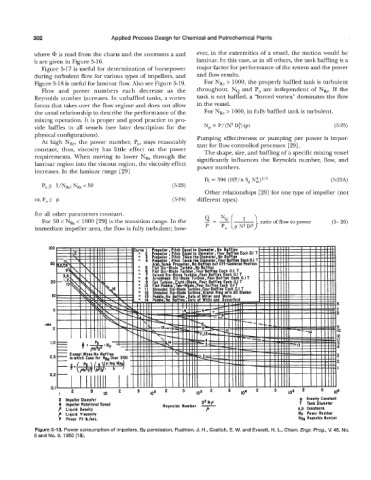
Figure 5-13. Power consumption of impellers. By permission, Rushton, J. H., Costich, E. W. and Everett, H. L., Chem. Engr. Prog., V. 46, No.
8 and No. 9, 1950 [18].