
Page 161 - 05. Subyek Teknik Mesin - Automobile Mechanical and Electrical Systems Automotive Technology Vehicle Maintenance and Repair (Vehicle Maintenance Repr Nv2) by Tom Denton
P. 161
2
Engine systems 145
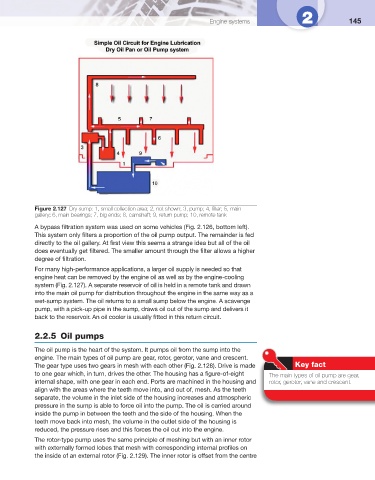
Figure 2.127 Dry sump: 1, small collection area; 2, not shown; 3, pump; 4, fi lter; 5, main
gallery; 6, main bearings; 7, big ends; 8, camshaft; 9, return pump; 10, remote tank
A bypass fi ltration system was used on some vehicles ( Fig. 2.126 , bottom left).
This system only fi lters a proportion of the oil pump output. The remainder is fed
directly to the oil gallery. At fi rst view this seems a strange idea but all of the oil
does eventually get fi ltered. The smaller amount through the fi lter allows a higher
degree of fi ltration.
For many high-performance applications, a larger oil supply is needed so that
engine heat can be removed by the engine oil as well as by the engine-cooling
system ( Fig. 2.127 ). A separate reservoir of oil is held in a remote tank and drawn
into the main oil pump for distribution throughout the engine in the same way as a
wet-sump system. The oil returns to a small sump below the engine. A scavenge
pump, with a pick-up pipe in the sump, draws oil out of the sump and delivers it
back to the reservoir. An oil cooler is usually fi tted in this return circuit.
2.2.5 Oil pumps
The oil pump is the heart of the system. It pumps oil from the sump into the
engine. The main types of oil pump are gear, rotor, gerotor, vane and crescent.
The gear type uses two gears in mesh with each other ( Fig. 2.128 ). Drive is made Key fact
to one gear which, in turn, drives the other. The housing has a fi gure-of-eight The main types of oil pump are gear,
internal shape, with one gear in each end. Ports are machined in the housing and rotor, gerotor, vane and crescent.
align with the areas where the teeth move into, and out of, mesh. As the teeth
separate, the volume in the inlet side of the housing increases and atmospheric
pressure in the sump is able to force oil into the pump. The oil is carried around
inside the pump in between the teeth and the side of the housing. When the
teeth move back into mesh, the volume in the outlet side of the housing is
reduced, the pressure rises and this forces the oil out into the engine.
The rotor-type pump uses the same principle of meshing but with an inner rotor
with externally formed lobes that mesh with corresponding internal profi les on
the inside of an external rotor ( Fig. 2.129 ). The inner rotor is offset from the centre