
Page 172 - 05. Subyek Teknik Mesin - Automobile Mechanical and Electrical Systems Automotive Technology Vehicle Maintenance and Repair (Vehicle Maintenance Repr Nv2) by Tom Denton
P. 172
2
156 Automobile mechanical and electrical systems
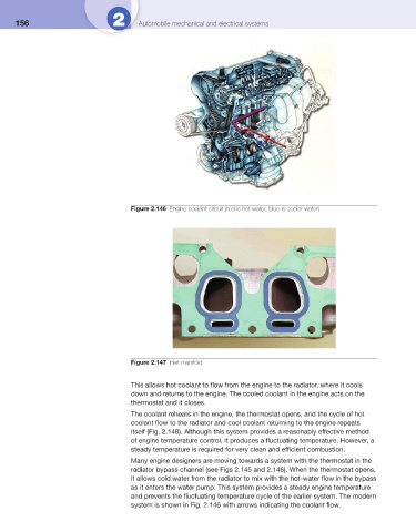
Figure 2.146 Engine coolant circuit (red is hot water, blue is cooler water)
Figure 2.147 Inlet manifold
This allows hot coolant to fl ow from the engine to the radiator, where it cools
down and returns to the engine. The cooled coolant in the engine acts on the
thermostat and it closes.
The coolant reheats in the engine, the thermostat opens, and the cycle of hot
coolant fl ow to the radiator and cool coolant returning to the engine repeats
itself ( Fig. 2.148 ). Although this system provides a reasonably effective method
of engine temperature control, it produces a fl uctuating temperature. However, a
steady temperature is required for very clean and effi cient combustion.
Many engine designers are moving towards a system with the thermostat in the
radiator bypass channel (see Figs 2.145 and 2.146 ). When the thermostat opens,
it allows cold water from the radiator to mix with the hot-water fl ow in the bypass
as it enters the water pump. This system provides a steady engine temperature
and prevents the fl uctuating temperature cycle of the earlier system. The modern
system is shown in Fig. 2.146 with arrows indicating the coolant fl ow.