
Page 171 - 05. Subyek Teknik Mesin - Automobile Mechanical and Electrical Systems Automotive Technology Vehicle Maintenance and Repair (Vehicle Maintenance Repr Nv2) by Tom Denton
P. 171
2
Engine systems 155
The main areas where cooling is needed are around the combustion chambers
and the upper cylinder walls ( Fig. 2.144 ). The need for inlet ports, exhaust ports
and valves makes cooling of these regions diffi cult. These areas are prone Key fact
to cracking and other deterioration from overheating, freezing and the use of The internal designs of the head and
incorrect, or old, antifreeze solutions. block vary to give different coolant
fl ow patterns.
Developments in coolant circulation give improved control of engine temperature
( Figs 2.145 and 2.146 ). Mixing cold and hot water as it enters the engine
achieves this, as opposed to the cold fi ll of earlier systems.
Many engines use a heated inlet manifold that has a coolant fl ow from the engine
water jacket running continuously through it ( Fig. 2.147 ). As soon as an engine is
started, some heat is produced and this rises into the inlet manifold very quickly.
The heat vaporizes the fuel in the air stream into the engine. This improves
atomization and fuel distribution in the new air and fuel charge.
Liquid cooling systems traditionally used a thermostat in the outlet to the top
hose to control engine temperature. A thermostat is a temperature-sensing
valve that opens when the coolant is hot and closes as the coolant cools down.
Figure 2.144 Cylinder head coolant passages
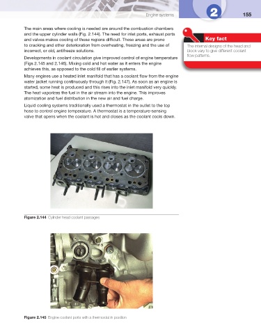
Figure 2.145 Engine coolant ports with a thermostat in position