
Page 174 - 05. Subyek Teknik Mesin - Automobile Mechanical and Electrical Systems Automotive Technology Vehicle Maintenance and Repair (Vehicle Maintenance Repr Nv2) by Tom Denton
P. 174
2
158 Automobile mechanical and electrical systems
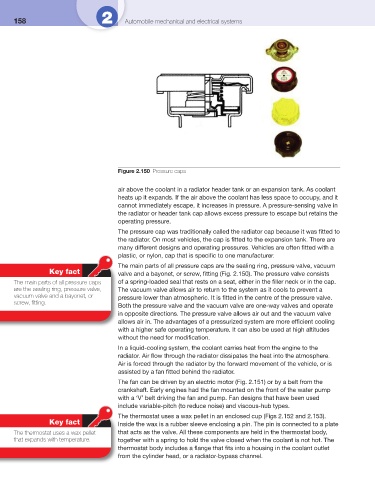
Figure 2.150 Pressure caps
air above the coolant in a radiator header tank or an expansion tank. As coolant
heats up it expands. If the air above the coolant has less space to occupy, and it
cannot immediately escape, it increases in pressure. A pressure-sensing valve in
the radiator or header tank cap allows excess pressure to escape but retains the
operating pressure.
The pressure cap was traditionally called the radiator cap because it was fi tted to
the radiator. On most vehicles, the cap is fi tted to the expansion tank. There are
many different designs and operating pressures. Vehicles are often fi tted with a
plastic, or nylon, cap that is specifi c to one manufacturer.
The main parts of all pressure caps are the sealing ring, pressure valve, vacuum
Key fact valve and a bayonet, or screw, fi tting ( Fig. 2.150 ). The pressure valve consists
The main parts of all pressure caps of a spring-loaded seal that rests on a seat, either in the fi ller neck or in the cap.
are the sealing ring, pressure valve, The vacuum valve allows air to return to the system as it cools to prevent a
vacuum valve and a bayonet, or pressure lower than atmospheric. It is fi tted in the centre of the pressure valve.
screw, fi tting.
Both the pressure valve and the vacuum valve are one-way valves and operate
in opposite directions. The pressure valve allows air out and the vacuum valve
allows air in. The advantages of a pressurized system are more effi cient cooling
with a higher safe operating temperature. It can also be used at high altitudes
without the need for modifi cation.
In a liquid-cooling system, the coolant carries heat from the engine to the
radiator. Air fl ow through the radiator dissipates the heat into the atmosphere.
Air is forced through the radiator by the forward movement of the vehicle, or is
assisted by a fan fi tted behind the radiator.
The fan can be driven by an electric motor ( Fig. 2.151 ) or by a belt from the
crankshaft. Early engines had the fan mounted on the front of the water pump
with a ‘V’ belt driving the fan and pump. Fan designs that have been used
include variable-pitch (to reduce noise) and viscous-hub types.
The thermostat uses a wax pellet in an enclosed cup ( Figs 2.152 and 2.153 ).
Key fact Inside the wax is a rubber sleeve enclosing a pin. The pin is connected to a plate
The thermostat uses a wax pellet that acts as the valve. All these components are held in the thermostat body,
that expands with temperature. together with a spring to hold the valve closed when the coolant is not hot. The
thermostat body includes a fl ange that fi ts into a housing in the coolant outlet
from the cylinder head, or a radiator-bypass channel.