
Page 321 - 05. Subyek Teknik Mesin - Automobile Mechanical and Electrical Systems Automotive Technology Vehicle Maintenance and Repair (Vehicle Maintenance Repr Nv2) by Tom Denton
P. 321
3
Electrical systems 303
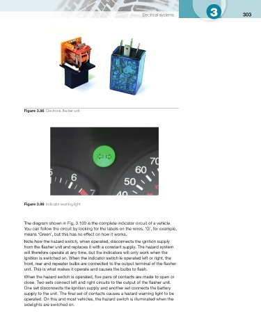
Figure 3.98 Electronic fl asher unit
Figure 3.99 Indicator warning light
The diagram shown in Fig. 3.100 is the complete indicator circuit of a vehicle.
You can follow the circuit by looking for the labels on the wires. ‘G’, for example,
means ‘Green’, but this has no effect on how it works.
Note how the hazard switch, when operated, disconnects the ignition supply
from the fl asher unit and replaces it with a constant supply. The hazard system
will therefore operate at any time, but the indicators will only work when the
ignition is switched on. When the indicator switch is operated left or right, the
front, rear and repeater bulbs are connected to the output terminal of the fl asher
unit. This is what makes it operate and causes the bulbs to fl ash.
When the hazard switch is operated, fi ve pairs of contacts are made to open or
close. Two sets connect left and right circuits to the output of the fl asher unit.
One set disconnects the ignition supply and another set connects the battery
supply to the unit. The fi nal set of contacts causes a hazard warning light to be
operated. On this and most vehicles, the hazard switch is illuminated when the
sidelights are switched on.