
Page 322 - 05. Subyek Teknik Mesin - Automobile Mechanical and Electrical Systems Automotive Technology Vehicle Maintenance and Repair (Vehicle Maintenance Repr Nv2) by Tom Denton
P. 322
3
304 Automobile mechanical and electrical systems
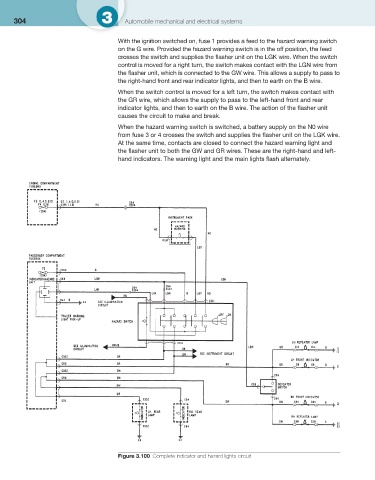
With the ignition switched on, fuse 1 provides a feed to the hazard warning switch
on the G wire. Provided the hazard warning switch is in the off position, the feed
crosses the switch and supplies the fl asher unit on the LGK wire. When the switch
control is moved for a right turn, the switch makes contact with the LGN wire from
the fl asher unit, which is connected to the GW wire. This allows a supply to pass to
the right-hand front and rear indicator lights, and then to earth on the B wire.
When the switch control is moved for a left turn, the switch makes contact with
the GR wire, which allows the supply to pass to the left-hand front and rear
indicator lights, and then to earth on the B wire. The action of the fl asher unit
causes the circuit to make and break.
When the hazard warning switch is switched, a battery supply on the N0 wire
from fuse 3 or 4 crosses the switch and supplies the fl asher unit on the LGK wire.
At the same time, contacts are closed to connect the hazard warning light and
the fl asher unit to both the GW and GR wires. These are the right-hand and left-
hand indicators. The warning light and the main lights fl ash alternately.
Figure 3.100 Complete indicator and hazard lights circuit