
Page 179 - Automotive Engineering Powertrain Chassis System and Vehicle Body
P. 179
Hybrid vehicle design CHAPTER 7.1
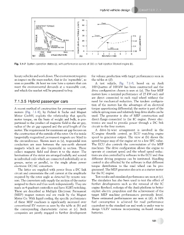
Fig. 7.1-7 System operation states (a), with performance curves of 300 cc fuel-injection Wankel engine (b).
luxury vehicles and work down. The environment requires for volume production with target performances seen in
an impact on the mass market, that is the ‘repmobile’, as the tables at (d).
soon as possible. At least we now have a system that can A test vehicle, Fig. 7.1-9, based on an Audi
meet the environmental demands at a reasonable cost, 100 Quattro of 100 kW has been constructed and the
and which the market will be prepared to buy. drive configuration chosen is seen at (a). The four MEP
motors have a nominal performance of 25 kW each and
are direct connected to each road wheel without the
7.1.3.5 Hybrid passenger cars need for mechanical reduction. The tandem configura-
tion of the motors has the advantages of an electrical
A recent method of construction for permanent magnet torque apportioning differential; the motor is part of the
motors (Fig. 7.1-8), by Fichtel & Sachs and Magnet vehicle sprung mass and relatively long drive shafts can be
Motor GmbH, exploits the relationship that specific used. The generator is also of MEP construction and
motor torque, on the basis of weight and bulk, is pro- direct-flange-connected to the IC engine. Power elec-
portional to the product of magnetic field in the air gap, tronics are used to provide power through a DC link
radius of the air gap squared and the axial length of the circuit to the four motors.
motor. The requirement for maximum air gap focuses on A drive-by-wire arrangement is involved in the
the construction of the outside of the rotor. On the inside IC-engine throttle control, an ECU matching engine
tangentially magnetized permanent magnets are fitted to speed to generator output. The view at (b) shows the
the circumference. Shown inset in (a), trapezoidal iron speed/torque map of the engine set to a low SFC value.
conductors are seen between the rare-earth element The ECU also controls the commutation of the MEP
magnets which are also trapezoidal in section. These machines. The drive configuration allows the engine to
collect magnetic field and divert it to the stator. The operate at constant speed and the wheel speed reduc-
laminations of the stator are arranged radially and wound tions are also controlled by software in the ECU and thus
in individual coils which are connected individually or in different driving programs can be instituted. Handling
groups, series or parallel, to the single phase power control is also affected by the software in that different
electronic DC/AC converters. torque distribution to the road wheel can be pro-
The latter are supplied with power from a DC link grammed. The MEP generator also acts as a starter motor
circuit and commutate the coil current at the amplitude for the IC engine.
required by the rotor angle as detected by remote sen- Test results and simulated performance are seen at (c).
sors. The converters only supply the section of the motor The simulation has also been used to test the effect of
assigned to them and thus work independently. They are further developments such as the removal of the IC
made as 4 quadrant controllers and have IGBTswitching. engine flywheel, redesign of the Audi platform to better
These are described as Multiple Electronic Permanent exploit electric propulsion and the achievement of the
(MEP) magnet motors and are made by the Magnet target MEP machine performances previously listed.
Motor Co. With liquid cooling, the specific performance These estimated performances are seen at (d). A 10%
of these MEP machines is significantly increased over fuel consumption is achieved for road performance
conventional EV motors as seen by the table at (b) and equivalent to the standard car and work is under way to
the corresponding characteristic curves at (c). Both design ULEV versions incorporating on-board storage
companies are jointly engaged in further development batteries.
181