
Page 175 - Automotive Engineering Powertrain Chassis System and Vehicle Body
P. 175
Hybrid vehicle design CHAPTER 7.1
to reduce weight is paramount in overcoming the 7.1.2.2 Justifying hybrid drive
problem of the redundant drive in hybrid designs.
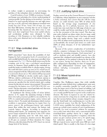
A useful analysis of over 10 000 car journeys through- Studies carried out at the General Research Corporation
out Europe was undertaken for a better understanding of in California, where legislation on zero emission vehicles
‘mission profile’ for the driving cycles involved. Cars were is hotly contested, have shown that the 160 km range
found to be used typically between one and eight times electric car could electrify some 80% of urban travel
per day, as at (b), and total daily distances travelled were based on the average range requirements of city
mostly less than 55 km. Some 13% of trips, (c), were households, (a). It is unlikely, however, that a driver
less than 500 metres, showing that we are in danger of would take trips such that the full range of electric cars
becoming like the Americans who drive even to visit could be totally used before switching to the IC engine
their next door neighbours! Even more useful velocity car for the remainder of the day’s travel. This does not
and acceleration profiles were obtained, by data arise with a hybrid car whose entire electric range could
recoding at 1 Hz frequency, so that valuable synthetic be utilized before switching and it has been estimated
drive cycles were obtained such as the urban driving one that with similar electric range such a vehicle would
shown at (d). cover 96% of urban travel requirements. In two or more
car households, the second (and more) car could meet
100% of urban demand, if of the hybrid-drive type
(Fig. 7.1-4).
7.1.2.1 Map-controlled drive Because of the system complexities of hybrid-drive
management vehicles, computer techniques have been developed to
3
optimize the operating strategies. Ford researchers ,as
2
BMW researchers have shown the possibility of chal- well as studying series and parallel systems, have also
lenging the fuel consumption levels of conventional cars examined the combined series/parallel one shown at (b).
with parallel hybrid levels, by using map-controlled drive The complexity of the analysis is shown by the fact that
management, Fig. 7.1-3. The two-shaft system used by the in one system, having four clutches, there are 16 pos-
company, seen at (a), uses a rod-shaped asynchronous sible configurations depending on state of engagement.
motor, by Siemens, fitted parallel to the crankshaft be- They also differentiated between types with and
neath the intake manifold of the 4-cylinder engine, driving without wall-plug re-energization of the batteries
the tooth-belt drive system as seen at (b): overall specifi- between trips.
cation compared with the 518i production car from which
it is derived is shown at (c). The vehicle still has top speed
of 180 kph (100 kph in electric mode) and a range of 7.1.2.3 Mixed hybrid-drive
500 km; relative performance of the battery options is configurations
shown at (d).Electric servo pumps forsteering andbraking
systems are specified for the hybrid vehicle and a cooling Coauthor Ron Hodkinson argues that while initially
system for the electric motor is incorporated. The motor is parallel and series hybrid-drive configurations were seen
energized by the battery via a 13.8 V/50 A DC/DC con- as possible contenders (parallel for small vehicles and
verter. The key electronic control unit links with the main series for larger ones) it has been found in building ‘real
systems of the vehicle as seen at (e). world’ vehicles that a mixture of the two is needed. For
To implement the driving modes of either hybrid, cars a mainly parallel layout is required with a small series
electric or IC engine the operating strategy is broken element. The latter is required in case the vehicle be-
down into tasks processed parallel to one another by the comes stationary for a long time in a traffic jam to make
CPU, to control and monitor engine, motor, battery and sure the traction battery always remains charged to sus-
electric clutch. The mode task determines which traction tain the ‘hotel loads’ (air conditioning etc.) on the vehi-
condition is appropriate, balancing the inputs from the cle’s electrical system. Cars like the Toyota Prius have
power sources; the performance/output task controls 3–4 kW series capability but detail configuration of the
power flow within the total system; the battery task system as a whole is just a matter of cost vs performance.
controls battery charging. According to accelerator/ Generally the most economical solution for passenger
braking pedal inputs, the monitoring unit transfers the cars is with front wheel drive and a conventional differ-
power target required by the driver to the CPU where ential/final-drive gearbox driven by a single electric
the optimal operating point for both drive units is motor. No change-speed gearbox is required, where the
calculated in a continuous, iterative process. The graphs motor can give constant power over a 4:1 speed range,
at (f) give an example of three iterations for charge but reduction gearing is required to match 13
efficiency, also determined by the CPU, based on current 500 rpm typical motor speed with some 800 rpm road-
charge level of the battery. wheel speed. This is usually in the form of a two-stage
177