
Page 315 - Automotive Engineering Powertrain Chassis System and Vehicle Body
P. 315
CHAP TER 1 0. 1 Tyres and wheels
1.0
Dry
0.8 0.2 mm
Lateral coefficient of friction µ Y,W 0.4 1.0 mm
0.6
2.0 mm
Water film level
0.2
Depth of profile
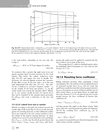
Fig. 10.1-47 Possible lateral friction coefficients m Y,W of a steel radial tyre 155 R 13 78 S depending on the depth of the tyre profile
as a percentage (starting from 8 mm ¼ 100%) at p T ¼ 1.8 bar, a ¼ 10 , v ¼ 60 km/h and varying water film levels in mm. The improved
grip of the treadless tyre on a dry road can be seen clearly as can its significantly poorer grip in the wet; a fact which also applies
to the coefficient of friction in the longitudinal direction (see Section 10.1.7.2).
a dry road surface, depending on the tyre size, the greater slip angles must be applied to maintain the bal-
change is ance of forces on the part of the tyres.
The average force F 3w with the standard camber values
DF Y;W;3 ¼ 40 N to 70 N per degree of camber
for individual wheel suspensions on a dry road are (see
(10.1.16) Section 10.1.2.3):
To counteract this, a greater slip angle must occur and (10.1.17)
F 3 W zF Z;W sin 3 W
greater steering input becomes necessary for the front
wheels. This makes the vehicle understeer more 10.1.9 Resulting force coefficient
(Fig. 10.1-41) and appear less easy to handle. Fur-
thermore, the steering aligning moment also increases.
If this effect occurs on the rear axles – as is the case Rolling resistance increases when negotiating a bend
with longitudinal link axles (Fig. 10.1-14) – the vehi- (see Equation 10.1.4a), and the vehiclewould decelerateif
an increased traction force F X,W,A did not create the
cle has a tendency to oversteer. Negative camber 3 w
on the outside of the bend and positive þ3 W on the equilibrium needed to retain the cornering speed selected.
inside would have exactly the opposite effect. Wheels F X,W,A is dependent on a series of factors and the type of
set in this manner would increase the lateral forces drive system (front- or rear-wheel drive); on single-axle
that can be absorbed by the amount stated previously drive (see Sections 8.1.4–8.1.6), the traction force on the
for DF Y,W,3 and cause a reduction in the tyre slip ground stresses the force coefficient of friction (the
angle. coefficient of)
m X;W ¼ F X;W;A;f; or r =F Z;V;for r (10.1.15)
10.1.8.5.6 Lateral force due to camber
and thus greater slip angles at the driven wheels. With
Wheels according to the body roll inclined towards the given values for cornering speed and radius (see Equation
outside edge of the bend (Fig. 8.1-6) try to roll outwards 10.1.8) the resulting force coefficient m rsl can be
against the steering direction, so that additional camber determined:
forces are required in the tyre contact patches to force
the wheels in the desired steering direction. As these 2 2 1
camber forces act in the same direction as the centrifugal m rsl ¼ðm Y;W þ m X;W Þ 2 (10.1.18)
force F c , Bo or V in the case described, greater lateral slip m rsl cannot be exceeded because the level depends on the
forces F Y,W,f,o , F Y,W,f,i ,F Y,W,r,o and F Y,W,r,i and hence road’s surface and the condition.
316