
Page 316 - Automotive Engineering Powertrain Chassis System and Vehicle Body
P. 316
Tyres and wheels C HAPTER 10.1
When braking on a bend, additional longitudinal In the longitudinal direction the possible braking force
forces F X,W,b occur on all wheels, and act against the F X , W , b ¼ 3130 N is at a ¼ 0 and therefore (see Equation
direction of travel. In this case Equation 10.1.18 also 10.1.5),
applies.
On standard vehicles and front-wheel drives, the m X;W;max ¼ F X;W;b =F Z;W ¼ 3130=2940ðN=NÞ
front wheels take 70–80% of the braking force and the ¼ 1:06
rear wheels only 20–30%. This means that the slip
angles increase on both axles, but more at the front and
than the rear and the vehicle tends to understeer 0:5 1
(Fig. 10.1-41). If the wheels of an axle lock, the fric- m X;W ¼ 1:06 1 2 2
tion becomes sliding friction and the vehicle pushes 0:97
with this pair of wheels towards the outside of the ¼ 0:91
bend. The lateral forces that the tyre can absorb during braking
Taking into consideration the maximum possible values can also be calculated:
in the longitudinal and lateral direction of the road –
known respectively as m X,W,max and m X,W,min – the m X;W 1 2
2
increasing force coefficient can be calculated: m Y;W ¼ m Y;W;max 1 m X;W;max (10.1.19a)
1
m Y;W 2 2 m X,W ¼ 0.7 should be given. The lateral force coefficient
m X;W ¼ m X;W;max 1 (10.1.19)
m Y;W;max (which can be used) is:
0:7 2 1 2
m ¼ 0:97 1
Consider as an example a braking process on a dry road at Y;W 1:06
100 km/h on a bend with R ¼ 156 m. Using Equation ¼ 0:73
10.1.9 the calculation gives m Y,W ¼ 0.5.
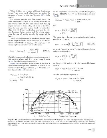
Figure 10.1-48 shows a measurement on the tyre in At S X,W,b ¼10% and a ¼ 4 the transferable lateral
question where the greatest coefficient of friction in the force is:
lateral direction at F Z,W ¼ 2490 N, 3 w ¼ 10% and a ¼ 4 F Y;W ¼ m F Z;W ¼ 0:73 2940
(see Equation 10.1.11) amounts to Y;W
¼ 2146 N
m Y;W;max ¼ F Y;W =F Z;W and the available braking force is:
¼ 2850=2940 ðN=NÞ
F X;W;b ¼ m X;W F Z;M ¼ 0:7 2940
m Y;W;max ¼ 0:97 ¼ 2058 N
Fig. 10.1-48 Tyre-tangential lateral force performance characteristics with slip angles and brake slip as parameters. The study was
carried out on a 18565 R 14 86 S radial tyre loaded at 300 kg at p T ¼ 1.5 bar. The shape of the curves indicates that, with increasing
longitudinal forces, those which can be absorbed laterally reduce. At 1.5 bar, the tyre carries a weight of 350 kg, i.e. it is only operating at
86% capacity.
317