
Page 321 - Automotive Engineering Powertrain Chassis System and Vehicle Body
P. 321
CHAP TER 1 0. 1 Tyres and wheels
steer effects depend on the size of the change in the
longitudinal force, the adherence potential between the
tyres and the road, the tyres and the kinematic and
elastokinematic chassis design.
10.1.12.1 Torque steer effects as a result
of changes in normal force
Torque steer effects usually occur during cornering when
a driver has to slow down on a wrongly assessed bend by
reducing the amount of acceleration or applying the
brake.
The reaction force acting at the centre of gravity of the
vehicle causes an increase in front axle load with a
simultaneous reduction in the load on the rear axle. At
an initially unchanged slip angle, the distribution of
lateral forces changes as a result. If the force coefficient
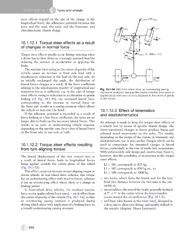
relating to the simultaneous transfer of longitudinal and Fig. 10.1-54 With front-wheel drive, an oversteering yawing
transverse forces is sufficient, e.g. in the case of torque moment is produced, because the resultant tractive force vector is
steer effects owing to reduction in acceleration or gentle applied about lever arm l f X sin d f displaced to the centre of gravity
braking (cf. Fig. 10.1-48), the increased lateral force of the vehicle.
corresponding to the increase in normal force on
the front axle results in a yawing moment which allows
the vehicle to turn into the bend. 10.1.12.3 Effect of kinematics
If the adhesion potential is exceeded as a result of and elastokinematics
fierce braking or a low force coefficient, the tyres are no
longer able to build up the necessary lateral forces. This An attempt is made to keep the torque steer effects of
results in an over- or understeering vehicle response a vehicle low by means of specific chassis design. The
depending on the specific case, be it a loss of lateral force above-mentioned changes in forces produce bump and
on the front axle or rear axle or both. rebound travel movements on the axles. The results,
depending on the design of the chassis, in kinematic and
elastokinematic toe-in and camber changes which can be
10.1.12.2 Torque steer effects resulting used to compensate for unwanted changes in lateral
from tyre aligning torque forces, particularly in the case of multi-link suspensions.
With unfavourable axle design and construction, there is,
The lateral displacement of the tyre contact area as however, also the possibility of an increase in the torque
a result of lateral forces leads to longitudinal forces steer effects.
being applied outside the centre plane of the wheel LI ¼ 101 corresponds to 825 kg,
(Fig. 10.1-53). LI ¼ 102 corresponds to 850 kg etc. to
This effect causes an increase in tyre aligning torque in LI ¼ 108 corresponds to 1000 kg.
driven wheels. In rear-wheel drive vehicles, this torque
has an understeering effect with tractive forces, whereas rim horns, which form the lateral seat for the tyre
it has an oversteering effect where there is a change in bead (the distance between the two rims is the jaw
braking power. width a);
In front-wheel drive vehicles, the resultant tractive rim shoulders, the seat of the beads, generally inclined
force vector applies about lever arm l f sin d f offset from at 5 1 to the centre where the force transfer
the centre of gravity of the vehicle (Fig. 10.1-54), so that occurs around the circumference (Fig. 10.1-5);
an oversteering yawing moment is produced during well base (also known as the inner base), designed as
driving which alters with application of a braking force to a drop rim to allow tyre fitting, and mostly shifted to
a (small) understeering yawing moment. the outside (diagram: Hayes Lemmerz).
322