
Page 43 - Automotive Engineering Powertrain Chassis System and Vehicle Body
P. 43
Measurement of torque, power, speed and fuel consumption CHAPTER 2.1
Lloyd’s give curves of T m in terms of the indicated
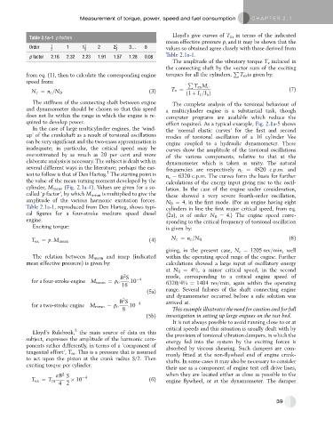
Table 2.1a-1 p factors
mean effective pressure p i and it may be shown that the
Order 1 1 1 1 2 2 1 3. 8 values so obtained agree closely with those derived from
2 2 2
Table 2.1a-1.
p factor 2.16 2.32 2.23 1.91 1.57 1.28 0.08
The amplitude of the vibratory torque T v induced in
the connecting shaft by the vector sum of the exciting
P
from eq. (1), then to calculate the corresponding engine torques for all the cylinders, T ex is given by:
speed from: P
T ex M c
(3) T v ¼ (7)
N c ¼ n c =N 0 ð1 þ I e =I Þ
b
The stiffness of the connecting shaft between engine The complete analysis of the torsional behaviour of
and dynamometer should be chosen so that this speed a multicylinder engine is a substantial task, though
does not lie within the range in which the engine is re- computer programs are available which reduce the
quired to develop power. effort required. As a typical example, Fig. 2.1a-5 shows
In the case of large multicylinder engines, the ‘wind- the ‘normal elastic curves’ for the first and second
up’ of the crankshaft as a result of torsional oscillations modes of torsional oscillation of a 16 cylinder Vee
can be very significant and the two-mass approximation is engine coupled to a hydraulic dynamometer. These
inadequate; in particular, the critical speed may be curves show the amplitude of the torsional oscillations
overestimated by as much as 20 per cent and more of the various components, relative to that at the
elaborate analysis is necessary. The subject is dealt with in dynamometer which is taken as unity. The natural
several different ways in the literature; perhaps the eas- frequencies are respectively n c ¼ 4820 c.p.m. and
1
iest to follow is that of Den Hartog. The starting point is n c ¼ 6320 c.p.m. The curves form the basis for further
the value of the mean turning moment developed by the calculations of the energy input giving rise to the oscil-
cylinder, M mean (Fig. 2.1a-4). Values are given for a so- lation. In the case of the engine under consideration,
called ‘p factor’, by which M mean is multiplied to give the these showed a very severe fourth-order oscillation,
amplitude of the various harmonic excitation forces. N 0 ¼ 4, in the first mode. (For an engine having eight
Table 2.1a-1, reproduced from Den Hartog, shows typi- cylinders in line the first major critical speed, from eq.
cal figures for a four-stroke medium speed diesel (2a), is of order N 0 ¼ 4.) The engine speed corre-
engine. sponding to the critical frequency of torsional oscillation
Exciting torque: is given by:
T ex ¼ p: M mean (4) N c ¼ n c =N 0 (8)
giving, in the present case, N c ¼ 1205 rev=min, well
The relation between M mean and imep (indicated within the operating speed range of the engine. Further
mean effective pressure) is given by: calculations showed a large input of oscillatory energy
at N 0 ¼ 4½, a minor critical speed, in the second
2
B S mode, corresponding to a critical engine speed of
for a four-stroke engine M mean ¼ p i : :10 4
16 6320/4¼ ¼ 1404 rev/min, again within the operating
range. Several failures of the shaft connecting engine
(5a)
and dynamometer occurred before a safe solution was
2
B S 4 arrived at.
for a two-stroke engine M mean ¼ p i : :10
8 This example illustrates the need for caution and for full
(5b) investigation in setting up large engines on the test bed.
It is not always possible to avoid running close to or at
critical speeds and this situation is usually dealt with by
5
Lloyd’s Rulebook, the main source of data on this the provision of torsional vibration dampers, in which the
subject, expresses the amplitude of the harmonic com- energy fed into the system by the exciting forces is
ponents rather differently, in terms of a ‘component of absorbed by viscous shearing. Such dampers are com-
tangential effort’, T m . This is a pressure that is assumed monly fitted at the non-flywheel end of engine crank-
to act upon the piston at the crank radius S/2. Then shafts. In some cases it may also be necessary to consider
exciting torque per cylinder:
their use as a component of engine test cell drive lines,
2
pB S 4 when they are located either as close as possible to the
T ex ¼ T m 10 (6) engine flywheel, or at the dynamometer. The damper
4 2
39