
Page 44 - Automotive Engineering Powertrain Chassis System and Vehicle Body
P. 44
CH AP TER 2 .1 Measurement of torque, power, speed and fuel consumption
4
3
Second mode 6320 c.p.m.
Dynamometer
2
1 Flange Flywheel
Relative amplitude 0 Cylinder 1 2 3 4 5 6 7 8
–1
Damper Damper hub
–2
First mode 4820 c.p.m.
–3
–4
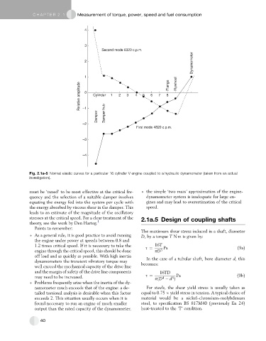
Fig. 2.1a-5 Normal elastic curves for a particular 16 cylinder V engine coupled to a hydraulic dynamometer (taken from an actual
investigation).
must be ‘tuned’ to be most effective at the critical fre- the simple ‘two mass’ approximation of the engine-
quency and the selection of a suitable damper involves dynamometer system is inadequate for large en-
equating the energy fed into the system per cycle with gines and may lead to overestimation of the critical
the energy absorbed by viscous shear in the damper. This speed.
leads to an estimate of the magnitude of the oscillatory
stresses at the critical speed. For a clear treatment of the 2.1a.5 Design of coupling shafts
theory, see the work by Den Hartog. 1
Points to remember:
The maximum shear stress induced in a shaft, diameter
As a general rule, it is good practice to avoid running D, by a torque T N m is given by:
the engine under power at speeds between 0.8 and
1.2 times critical speed. If it is necessary to take the s ¼ 16T Pa (9a)
engine through the critical speed, this should be done pD 3
off load and as quickly as possible. With high inertia In the case of a tubular shaft, bore diameter d, this
dynamometers the transient vibratory torque may becomes:
well exceed the mechanical capacity of the drive line
and the margin of safety of the drive line components 16TD
may need to be increased. s ¼ 4 4 Pa (9b)
pðD d Þ
Problems frequently arise when the inertia of the dy-
namometer much exceeds that of the engine: a de- For steels, the shear yield stress is usually taken as
tailed torsional analysis is desirable when this factor equal to 0.75 yield stress in tension. A typical choice of
exceeds 2. This situation usually occurs when it is material would be a nickel–chromium–molybdenum
found necessary to run an engine of much smaller steel, to specification BS 817M40 (previously En 24)
output than the rated capacity of the dynamometer. heat-treated to the ‘T’ condition.
40