
Page 46 - Automotive Engineering Powertrain Chassis System and Vehicle Body
P. 46
CH AP TER 2 .1 Measurement of torque, power, speed and fuel consumption
steady bearings at the centre of flexible couplings in high-
speed applications, but these are liable to give fretting
problems and are not universally favoured.
As is well known, the whirling speed of a shaft is
identical with its natural frequency of transverse oscil-
lation. To allow for the effect of transverse coupling
flexibility the simplest procedure is to calculate the
transverse critical frequency of the shaft plus two half
couplings from the equation:
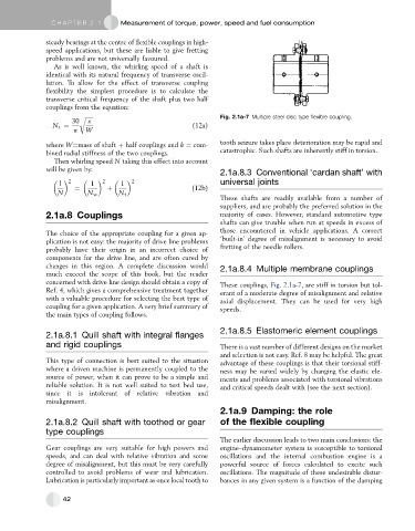
r ffiffiffiffiffiffi Fig. 2.1a-7 Multiple steel disc type flexible coupling.
30 k
N t ¼ (12a)
p W
where W¼mass of shaft þ half couplings and k ¼ com- tooth seizure takes place deterioration may be rapid and
bined radial stiffness of the two couplings. catastrophic. Such shafts are inherently stiff in torsion.
Then whirling speed N taking this effect into account
will be given by:
2.1a.8.3 Conventional ‘cardan shaft’ with
2 2 2
1 1 1 universal joints
¼ þ (12b)
N N w N t
These shafts are readily available from a number of
suppliers, and are probably the preferred solution in the
2.1a.8 Couplings majority of cases. However, standard automotive type
shafts can give trouble when run at speeds in excess of
The choice of the appropriate coupling for a given ap- those encountered in vehicle applications. A correct
plication is not easy: the majority of drive line problems ‘built-in’ degree of misalignment is necessary to avoid
probably have their origin in an incorrect choice of fretting of the needle rollers.
components for the drive line, and are often cured by
changes in this region. A complete discussion would 2.1a.8.4 Multiple membrane couplings
much exceed the scope of this book, but the reader
concerned with drive line design should obtain a copy of These couplings, Fig. 2.1a-7, are stiff in torsion but tol-
Ref. 4, which gives a comprehensive treatment together erant of a moderate degree of misalignment and relative
with a valuable procedure for selecting the best type of axial displacement. They can be used for very high
coupling for a given application. A very brief summary of speeds.
the main types of coupling follows.
2.1a.8.5 Elastomeric element couplings
2.1a.8.1 Quill shaft with integral flanges
and rigid couplings There is a vast number of different designs on the market
and selection is not easy. Ref. 8 may be helpful. The great
This type of connection is best suited to the situation advantage of these couplings is that their torsional stiff-
where a driven machine is permanently coupled to the ness may be varied widely by changing the elastic ele-
source of power, when it can prove to be a simple and ments and problems associated with torsional vibrations
reliable solution. It is not well suited to test bed use, and critical speeds dealt with (see the next section).
since it is intolerant of relative vibration and
misalignment.
2.1a.9 Damping: the role
2.1a.8.2 Quill shaft with toothed or gear of the flexible coupling
type couplings
The earlier discussion leads to two main conclusions: the
Gear couplings are very suitable for high powers and engine–dynamometer system is susceptible to torsional
speeds, and can deal with relative vibration and some oscillations and the internal combustion engine is a
degree of misalignment, but this must be very carefully powerful source of forces calculated to excite such
controlled to avoid problems of wear and lubrication. oscillations. The magnitude of these undesirable distur-
Lubrication is particularly important as once local tooth to bances in any given system is a function of the damping
42