
Page 64 - Automotive Engineering Powertrain Chassis System and Vehicle Body
P. 64
Emissions control CHAPTER 3.1
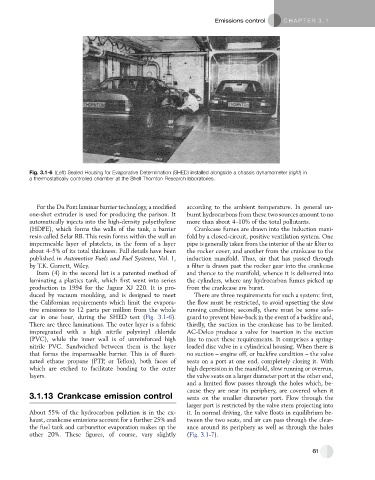
Fig. 3.1-6 (Left) Sealed Housing for Evaporative Determination (SHED) installed alongside a chassis dynamometer (right)in
a thermostatically controlled chamber at the Shell Thornton Research laboratories.
For the Du Pont laminar barrier technology, a modified according to the ambient temperature. In general un-
one-shot extruder is used for producing the parison. It burnt hydrocarbons from these two sources amount to no
automatically injects into the high-density polyethylene more than about 4–10% of the total pollutants.
(HDPE), which forms the walls of the tank, a barrier Crankcase fumes are drawn into the induction mani-
resin called Selar RB. This resin forms within the wall an fold by a closed-circuit, positive ventilation system. One
impermeable layer of platelets, in the form of a layer pipe is generally taken from the interior of the air filter to
about 4–5% of its total thickness. Full details have been the rocker cover, and another from the crankcase to the
published in Automotive Fuels and Fuel Systems, Vol. 1, induction manifold. Thus, air that has passed through
by T.K. Garrett, Wiley. a filter is drawn past the rocker gear into the crankcase
Item (4) in the second list is a patented method of and thence to the manifold, whence it is delivered into
laminating a plastics tank, which first went into series the cylinders, where any hydrocarbon fumes picked up
production in 1994 for the Jaguar XJ 220. It is pro- from the crankcase are burnt.
duced by vacuum moulding, and is designed to meet There are three requirements for such a system: first,
the Californian requirements which limit the evapora- the flow must be restricted, to avoid upsetting the slow
tive emissions to 12 parts per million from the whole running condition; secondly, there must be some safe-
car in one hour, during the SHED test (Fig. 3.1-6). guard to prevent blow-back in the event of a backfire and,
There are three laminations. The outer layer is a fabric thirdly, the suction in the crankcase has to be limited.
impregnated with a high nitrile polyvinyl chloride AC-Delco produce a valve for insertion in the suction
(PVC), while the inner wall is of unreinforced high line to meet these requirements. It comprises a spring-
nitrile PVC. Sandwiched between them is the layer loaded disc valve in a cylindrical housing. When there is
that forms the impermeable barrier. This is of fluori- no suction – engine off, or backfire condition – the valve
nated ethane propane (FTP, or Teflon), both faces of seats on a port at one end, completely closing it. With
which are etched to facilitate bonding to the outer high depression in the manifold, slow running or overrun,
layers. the valve seats on a larger diameter port at the other end,
and a limited flow passes through the holes which, be-
cause they are near its periphery, are covered when it
3.1.13 Crankcase emission control seats on the smaller diameter port. Flow through the
larger port is restricted by the valve stem projecting into
About 55% of the hydrocarbon pollution is in the ex- it. In normal driving, the valve floats in equilibrium be-
haust, crankcase emissions account for a further 25% and tween the two seats, and air can pass through the clear-
the fuel tank and carburettor evaporation makes up the ance around its periphery as well as through the holes
other 20%. These figures, of course, vary slightly (Fig. 3.1-7).
61