
Page 67 - Automotive Engineering Powertrain Chassis System and Vehicle Body
P. 67
CH AP TER 3 .1 Emissions control
There are also, however, even more complex air manage-
ment valves. The additional functions they perform are:
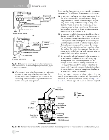
(5) In response to a low or zero depression signal from
the induction manifold, to divert the air pump
output to the air cleaner when the engine is oper-
ating under heavy load from nearly to fully open
throttle. This is to avoid the overheating of the
catalytic converter that would occur if the excess
hydrocarbon required to obtain maximum power
output were to be oxidised in it.
(6) In response to a high depression signal from the in-
duction manifold, to divert the air pump output to
the air cleaner during normal road load conditions.
This improves fuel consumption by decreasing ex-
haust back-pressure and, to a lesser degree, by re-
ducing the power required to operate the pump.
The air flow reverts to the exhaust manifold when
the load on the engine increases and therefore the
converter is needed to come back into operation to
control the hydrocarbon emissions.
(7) By means of a solenoid-actuated valve, to enable air
to be diverted by electronic control during any
driving mode. With this arrangement, the dia-
phragm valve is actuated by high depression and
Fig. 3.1-11 System for switching air from the manifold (a) for a spring, in the normal way, except when the elec-
open-loop operation to the oxidising catalytic converter, (b) for
closed-loop operation. tronic control opens the solenoid valve to introduce
air pump delivery pressure beneath the diaphragm
to override its spring return mode.
(4) Wherecontrolisexercisedbycomputer,thesolenoid-
actuated air switching valve diverts air from the There are other variants of these valves, but not
exhaust to the second stage catalytic converter for enough space here to describe them all. Their modes of
closed-loop operation or back again to the exhaust operation can be deduced from a study of Figs. 3.1-12
manifold for open-loop operation. to 3.1-14. Which type of valve is selected depends
Fig. 3.1-12 The Rochester normal diverter valve diverts air from the oxidising converter to the air cleaner for operation at heavy load.
64