
Page 116 - Automotive Engineering
P. 116
Transmissions and driveline CHAPTER 5.1
(a) (b) (c) (d) (e)
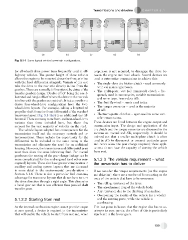
Fig. 5.1-1 Some typical vehicle/powertrain configurations.
(or all-wheel) drive power train frequently used in off- propulsion is not required, to disengage the drive be-
highway vehicles. The greater height of these vehicles tween the engine and road wheels. Several devices are
allows the engine to be mounted above the front axle line used in automotive transmissions to achieve this:
with the front differential alongside. Variants of this also The single-plate dry friction clutch – used commonly
take the drive to the rear axle directly in line from the with car manual gearboxes.
gearbox. These are normally differentiated by virtue of the The multi-plate, wet (oil immersed) clutch – fre-
transfer gearbox design. ‘Double offset’ being the one il- quently used in motorcycles, variable transmissions
lustrated and ‘single offset’ where the drive to the rear axle and some large, heavy-duty ATs.
is in line with the gearbox output shaft. It is also possible to The fluid flywheel – rarely used today.
derive four-wheel-drive configurations from the two-
wheel-drive layouts. For example, adding a longitudinal The torque converter – used in the majority
propeller shaft from the front differential of the standard of ATs.
transverse layout (Fig. 5.1-1(a)) to an additional rear dif- Electromagnetic clutches – again used in some vari-
ferential.There aremany more front-and rear-wheel-drive able transmissions.
variants than those included here, but these few These devices are fitted between the engine output and
account for the vast majority of vehicles on the road. transmission input. The design and application of the
The vehicle layout adopted has consequences for the dry clutch and the torque converter are discussed in the
transmission itself and the necessary controls and in- sections on manual and ATs, respectively. It should be
terconnections. These include the opportunity for the pointed out that a smaller multi-plate clutch is often
differential to be included in the same casing as the used in ATs to disconnect or connect particular gears
transmission and eliminate the need for an additional and hence allow the gear change required; these appli-
housing. However, the transmission and differential gears cations do not have the capacity of starting the vehicle
must then share the same lubricating fluid. For manual from rest.
gearboxes the routing of the gear-change linkage can be
more complicated for the mid-engined (and other rear- 5.1.2.3 The vehicle requirement – what
engined) layouts. These also have greater complication in the powertrain has to deliver
ancillary and cooling system layouts that are discussed
in more detail in the environmental considerations in If we consider the torque requirements (on the engine
Section 5.1.6. There is also a particular fuel economy and driveline), there are a number of forces acting on the
advantage for transverse layouts that do not have to turn body of the vehicle that have to be overcome:
the drive direction through a right angle. This eliminates
a bevel gear set that is less efficient than parallel shaft The rolling resistance of the tyres.
transfer gears. The aerodynamic drag of the vehicle body.
Any resistance due to the climbing of an incline.
Overcoming the inertia of the vehicle (as a whole)
5.1.2.2 Starting from rest and the rotating parts, while the vehicle is
accelerating.
As the internal combustion engine cannot provide torque This last point indicates that the engine also has to ac-
at zero speed, a device is required in the transmission celerate its own inertia; the effect of this is particularly
that will enable the vehicle to start from rest and, when significant in the lower gears.
109