
Page 30 - Automotive Engineering
P. 30
Measurement of torque, power, speed and fuel consumption CHAPTER 2.1
9 4 8 1 5 7 2 3
10 11 12 6 13 14
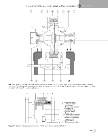
Fig. 2.1-3 Schenck, dry gap, disc type eddy-current dynamometer 1, rotor; 2, rotor shaft; 3, coupling flange; 4, water outlet with
thermostat; 5, excitation coil; 6, dynamometer housing; 7, cooling chamber; 8, air gap; 9, speed pick-up; 10, flexure support; 11, base;
12, water inlet; 13, joint; 14, water outlet pipe.
A 3 4 5 6 7 B
A = Mounting flange
B = Flange for torque
introduction
1 1 = Torsion element (rotor)
2 = Applied SGs
2 3 = Spindle bearing
4 = Housing (stator)
5 = Elastic seal
8 6 = Capacitive transmission
7 = Inductive transmission
8 = Toothed ring for speed
measurement
9
9 = Speed pick-up
10 10 = Cable connection box
Fig. 2.1-4 Brushless torque-shaft for mounting in shaft-line between engine and ‘brake’.
23