
Page 33 - Automotive Engineering
P. 33
CH AP TER 2 .1 Measurement of torque, power, speed and fuel consumption
carried out at the very least once a year, and following any within its associated electronics and display or, more
system change or major component replacement. recently, by use of an optical encoder system. While the
pulse pick-up system is robust and, providing the wheel
to transducer gap is correctly set and maintained, reli-
2.1.5 Torque measurement under
able, the optical encoders, which use the sensing of very
accelerating and decelerating fine lines etched on a small disk, need more care in
conditions mounting and operation. Since the commonly used op-
tical encoders transmit over 1000 pulses per revolution,
misalignment of its drive may show up as a sinusoidal
With the increasing interest in transient testing it is
essential to be aware of the effect of speed changes on speed change, therefore they are normally mounted as
the ‘apparent’ torque measured by a trunnion-mounted part of an accurately machined assembly forming part of
machine. the machine housing.
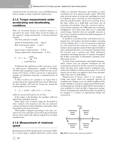
It should be remembered that with bidirectional dy-
The basic principle is simple: namometers and modern electrical machines operating
Inertia of dynamometer rotor I kg m 2 in four quadrants (Fig. 2.1-8), it is necessary to measure
Rate of increase in speed u rad/s 2 not only speed but also direction of rotation. Encoder
N rpm/s systems can use separate tracks of their engraved disks to
Input torque to dynamometer T l Nm sense rotational direction. It is extremely important that
Torque registered by dynamometer T 2 Nm the operator uses a common and clearly understood
convention describing direction of rotation throughout
2pNI the facility, particularly in laboratories operating rever-
T 1 T 2 ¼ Iu ¼ Nm
60 sible prime movers.
¼ 0:1047NI Nm As with torque measurement, specialized instrumen-
tation systems may use separate transducers for the
To illustrate the significance of this correction, a typi- measurement of speed or for the control of the dynamo-
cal eddy-current dynamometer capable of absorbing meter. In many cases, engine speed is monitored sepa-
150 kW with a maximum torque of 500 N m has a rotor rately and in addition to dynamometer speed. The control
2
inertia of 0.11 kg m . A direct current (d.c.) regenerative system can use these two signals to shut down automati-
machine of equivalent rating has a rotational inertia of cally in the case of a shaft failure.
2
0.60 kg m . Measurement of power, which is the product of
If these machines are coupled to an engine that is torque and speed, raises the important question of
accelerating at the comparatively slow rate of 100 rpm/s sampling time. Engines never run totally steadily and the
the first machine will read the torque low during the torque transducer and speed signals invariably fluctuate.
transient phase by an amount: An instantaneous reading of speed will not necessarily, or
even probably, be identical with a longer-term average.
T 1 T 2 ¼ 0:1047 100 0:11 ¼ 1:15 N m Choice of sampling time and of the number of samples to
be averaged is a matter of experimental design and
while the second will read low by 6.3 Nm. compromise.
If the engine is decelerating, the machines will read
high by the equivalent amount.
Much larger rates of speed change are demanded in
some transient test sequences and this can represent
a serious variation of torque indication, particularly when Torque
using high inertia dynamometers.
With modern computer processing of the data, cor- Anticlockwise, Clockwise,
rections for these and other electrically induced transient absorb absorb
effects can be made with software supplied by test plant torque torque
manufacturers. 2 1
Rotation
3 4
2.1.6 Measurement of rotational
Anticlockwise, Clockwise,
speed develop develop
torque torque
Rotational speed of the dynamometer is measured either
by a system using a toothed wheel and a pulse sensor Fig. 2.1-8 Dynamometer operating quadrants.
26