
Page 31 - Automotive Engineering
P. 31
CH AP TER 2 .1 Measurement of torque, power, speed and fuel consumption
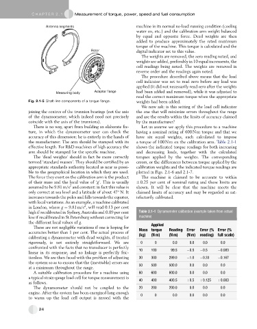
Antenna segments machine in its normal no-load running condition (cooling
water on, etc.) and the calibration arm weight balanced
by equal and opposite force. Dead weights are then
added to produce approximately the rated maximum
torque of the machine. This torque is calculated and the
Rotor digital indicator set to this value.
The weights are removed, the zero reading noted, and
weights are added, preferably in 10 equal increments, the
cell readings being noted. The weights are removed in
reverse order and the readings again noted.
The procedure described above means that the load
cell indicator was set to read zero before any load was
applied (it did not necessarily read zero after the weights
Measuring body Adaptor flange had been added and removed), while it was adjusted to
read the correct maximum torque when the appropriate
Fig. 2.1-5 Shaft-line components of a torque flange. weights had been added.
We now ask: is this setting of the load cell indicator
joining the centres of the trunnion bearings (not the axis the one that will minimize errors throughout the range
of the dynamometer, which indeed need not precisely and are the results within the limits of accuracy claimed
coincide with the axis of the trunnions). by the manufacturer?
There is no way, apart from building an elaborate fix- Let us assume we apply this procedure to a machine
ture, in which the dynamometer user can check the having a nominal rating of 600 N m torque and that we
accuracy of this dimension: he is entirely in the hands of have six equal weights, each calculated to impose
the manufacturer. The arm should be stamped with its a torque of 100 N m on the calibration arm. Table 2.1-1
effective length. For R&D machines of high accuracy the shows the indicated torque readings for both increasing
arm should be stamped for the specific machine. and decreasing loads, together with the calculated
The ‘dead weights’ should in fact be more correctly torques applied by the weights. The corresponding
termed ‘standard masses’. They should be certified by an errors, or the differences between torque applied by the
appropriate standards authority located as near as possi- calibration weights and the indicated torque readings are
ble to the geographical location in which they are used. plotted in Figs. 2.1-6 and 2.1-7.
The force they exert on the calibration arm is the product The machine is claimed to be accurate to within
of their mass and the local value of ‘g’. This is usually 0.25 per cent of nominal rating and these limits are
2
assumed to be 9.81 m/s and constant: in fact this value is shown. It will be clear that the machine meets the
only correct at sea level and a latitude of about 47 N. It claimed limits of accuracy and may be regarded as sat-
increases towards the poles and falls towards the equator, isfactorily calibrated.
with local variations. As an example, a machine calibrated
2
in London, where g ¼ 9.81 m/s , will read 0.13 per cent
high if recalibrated in Sydney, Australia and 0.09 per cent Table 2.1-1 Dynamometer calibration (example taken from actual
low if recalibrated in St Petersburg without correcting for machine)
the different local values of g.
These are not negligible variations if one is hoping for Applied
accuracies better than 1 per cent. The actual process of Mass torque Reading Error Error (% Error (%
(N m)
(N m)
(kg)
reading) full scale)
(N m)
calibrating a dynamometer with dead weights, if treated
rigorously, is not entirely straightforward. We are 0 0 0.0 0.0 0.0 0.0
confronted with the facts that no transducer is perfectly
10 100 99.5 0.5 0.5 0.083
linear in its response, and no linkage is perfectly fric-
tionless. We are then faced with the problem of adjusting 30 300 299.0 1.0 0.33 0.167
the system so as to ensure that the (inevitable) errors are
50 500 500.0 0.0 0.0 0.0
at a minimum throughout the range.
A suitable calibration procedure for a machine using 60 600 600.0 0.0 0.0 0.0
a typical strain-gauge load cell for torque measurement is
as follows. 40 400 400.5 þ0.5 þ0.125 þ0.083
The dynamometer should not be coupled to the 20 200 200.0 0.0 0.0 0.0
engine. After the system has been energized long enough 0 0 0.0 0.0 0.0 0.0
to warm up the load cell output is zeroed with the
24