
Page 70 - Automotive Engineering
P. 70
Emissions control CHAPTER 3.1
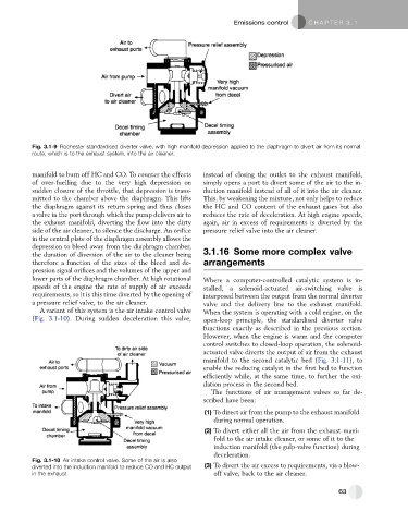
Fig. 3.1-9 Rochester standardised diverter valve, with high manifold depression applied to the diaphragm to divert air from its normal
route, which is to the exhaust system, into the air cleaner.
manifold to burn off HC and CO. To counter the effects instead of closing the outlet to the exhaust manifold,
of over-fuelling due to the very high depression on simply opens a port to divert some of the air to the in-
sudden closure of the throttle, that depression is trans- duction manifold instead of all of it into the air cleaner.
mitted to the chamber above the diaphragm. This lifts This, by weakening the mixture, not only helps to reduce
the diaphragm against its return spring and thus closes the HC and CO content of the exhaust gases but also
a valve in the port through which the pump delivers air to reduces the rate of deceleration. At high engine speeds,
the exhaust manifold, diverting the flow into the dirty again, air in excess of requirements is diverted by the
side of the air cleaner, to silence the discharge. An orifice pressure relief valve into the air cleaner.
in the central plate of the diaphragm assembly allows the
depression to bleed away from the diaphragm chamber,
the duration of diversion of the air to the cleaner being 3.1.16 Some more complex valve
therefore a function of the sizes of the bleed and de- arrangements
pression signal orifices and the volumes of the upper and
lower parts of the diaphragm chamber. At high rotational Where a computer-controlled catalytic system is in-
speeds of the engine the rate of supply of air exceeds stalled, a solenoid-actuated air-switching valve is
requirements, so it is this time diverted by the opening of interposed between the output from the normal diverter
a pressure relief valve, to the air cleaner. valve and the delivery line to the exhaust manifold.
A variant of this system is the air intake control valve When the system is operating with a cold engine, on the
(Fig. 3.1-10). During sudden deceleration this valve, open-loop principle, the standardised diverter valve
functions exactly as described in the previous section.
However, when the engine is warm and the computer
control switches to closed-loop operation, the solenoid-
actuated valve diverts the output of air from the exhaust
manifold to the second catalytic bed (Fig. 3.1-11), to
enable the reducing catalyst in the first bed to function
efficiently while, at the same time, to further the oxi-
dation process in the second bed.
The functions of air management valves so far de-
scribed have been:
(1) To direct air from the pump to the exhaust manifold
during normal operation.
(2) To divert either all the air from the exhaust mani-
fold to the air intake cleaner, or some of it to the
induction manifold (the gulp-valve function) during
deceleration.
Fig. 3.1-10 Air intake control valve. Some of the air is also
diverted into the induction manifold to reduce CO and HC output (3) To divert the air excess to requirements, via a blow-
in the exhaust. off valve, back to the air cleaner.
63